Basic Electrical, Electronics And Instrumentation Engineering: UNIT I: Electrical Circuits
Transmission And Distribution Of Electrical Energy
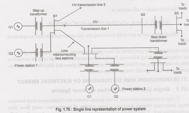
Trying to represent a practical power system where a lot of interconnections between several generating stations involving a large number of transformers using three lines corresponding to R, Y and B phase will become unnecessary clumsy and complicated.
TRANSMISSION
AND DISTRIBUTION OF ELECTRICAL ENERGY
Single Line
Representation of Power System
Trying
to represent a practical power system where a lot of interconnections between
several generating stations involving a large number of transformers using
three lines corresponding to R, Y and B phase will become unnecessary clumsy and
complicated. To avoid this, a single line along with some symbolical
representations for generator, transformers substation buses are used to
represent a power system rather neatly. For example, the system shown with
three lines will be simplified to Figure 1.75 using single line.
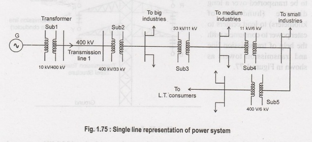
As
another example, an interconnected power system is represented in the self
explained Figure 1.75.
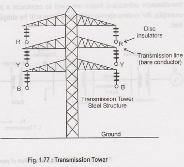
Transmission of power
power
generated in a power ilqmia od lliw station (hundreds of MW) is to be
transported over a long distance (hundreds of of kilometers) to load centers to
cater power to consumers with the help of transmission line and transmission
towers as shown in Figure 1.77.
To
give an idea, let us consider a generating station producing 120 MW power and
we want to transmit it over a large distance. Let the voltage generated (line
to line) at the alternator be 10 kV. Then to transmit 120 MW of power at 10 kV,
current in the transmission line can be easily calculated by using power
formula circuit (which you will learn in the lesson on A.C circuit analysis)
for 3-phases follows:
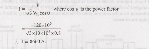
Instead
of choosing 10 kV transmission voltage, if transmission voltage were chosen to
be 400 kV, current value in the line would have been only 261.5 A. So sectional
area of the transmission line (copper conductor) will now be much smaller
compared to 10 kV transmission voltage. In other words the cost of conductor
will be greatly reduced if power is transmitted at higher and higher
transmission voltage. The use of higher voltage (hence lower current in the
line) reduces voltage drop in the line resistance and reactance. Also
transmission losses is reduced. Standard transmission voltages used are 132 kV
or 220 kV or 400 kV or 765 kV depending upon how long the transmission lines
are.
Therefore,
after the generator we must have a step up transformer to change the generated
voltage (say 10 kV) to desired transmission voltage (say 400 kV) before
transmitting it over a long distance with the help of transmission lines
supported at regular intervals by transmission towers. It should be noted that
while magnitude of current decides the cost of copper, level of voltage decides
the cost of insulators. The idea is, in a spree to reduce the cost of copper
one can not indefinitely increase the level of transmission voltage as cost of
insulators will offset the reduction copper cost. At the load centers voltage
level should be brought down at suitable values for supplying different types
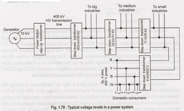
of consumers. Consumers may be (1) big industries, such as steel plants, (2)
medium and small industries and(3) offices and domestic consumers. Electricity
is purchased by different consumers at different voltage level. For example big
industries may purchase power at 132 kV, medium and big industries purchase
power at 33 kV or 11 kV and domestic consumers at rather low voltage of 230 V,
single phase. Thus we see that 400 kV transmission voltage is to be brought
down to different voltage levels before finally delivering power to different
consumers. To do this we require obviously step down transformers.
Substations
Substations
are the places where the level of voltage undergoes change with the help of
transformers. Apart from transformers a substation will house switches (called
circuit breakers), meters, relays for protection and other control equipment.
Broadly speaking, a big substation will receive power through incoming lines at
some voltage (say 400 kV) changes level of voltage (say to 132 kV) using a
transformer and then directs it out wards through outgoing lines. Pictorially
such a typical power system is shown in Figure 1.78 in a short of block
diagram. At the lowest voltage level of 400 V, generally 3-phase, 4-wire system
is adopted for domestic connections. The fourth wire is called the neutral wire
(N) which is taken out from the common point of the star connected secondary of
the 6 kV/400 V distribution transformer.
Some Important
Components/Equipments in Substation
As
told earlier, the function of a substation is to receive power at some voltage
through incoming lines and transmit it at some other voltage through outgoing
lines. So the most important equipment in a substation is transformer(s).
However, for flexibility of operation and protection transformer and lines
additional equipments are necessary.
Suppose
the transformer goes out of order and maintenance work is to be carried out.
Naturally the transformer must be isolated from the incoming as well as from
the outgoing lines by using special type of heavy duty (high voltage, high
current) switches called circuit breakers. Thus a circuit breaker may be closed
or opened manually (functionally somewhat similar to switching on or off a fan
or a light whenever desired with the help of a ordinary switch in your house)
in substation whenever desired. However unlike a ordinary switch, a circuit
breaker must also operate (i.e., become opened) automatically whenever a fault
occurs or overl iding takes place in a feeder or line. To achieve this, we must
have a current sensing device called CT (current transformer) in each line. A
CT simply steps down the large current to a proportional small secondary current.
Primary of the CT is connected in series with the line. A 1000 A/5 A CT will
step down the current by a factor of 200. So if primary current happens to be
800 A, secondary current of the CT will be 4 A.
Suppose
the rated current of the line is 1000 A, and due to any reason if current in
the line exceeds this limit we want to operate the circuit breaker
automatically for disconnection.
In
Figure 1.79 the basic scheme is presented to achieve this. The secondary
current of the CT is fed to the relay coil of an overcurrent relay. Here we are
not going into constructional and operational details of a over current relay
but try to tell how it functions. Depending upon the strength of the current in
the coil, an ultimately an electromagnetic torque acts on an aluminum disc
restrained by a spring. Spring tension is so adjusted that for normal current,
the disc does not move. However, if current exceeds the normal value, torque
produced will over come the spring tension to rotate the disc about a vertical
spindle to which a long arm is attached. To the arm a copper strip is attached
as shown Figure 1.80. Thus the arm too will move whenever the disk
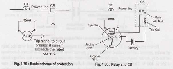
The
relay has a pair of normally opened (NO) contacts 1 and 2. Thus, there will
exist open circuit between 1 and 2 with normal current in the power line.
However, during fault condition in the line or overloading, the arm moves in
the anticlockwise direction till it closes the terminals 1 and 2 with the help
of the copper strip attached to the arm as explained pictorially in the Figure
1.29. This short circuit between 1 and 2 completes a circuit comprising of a
battery and the trip coil of the circuit breaker. The opening and closing of
the main contacts of the circuit breaker depends on whether its trip coil is
energized or not. It is interesting to note that trip circuit supply is to be
made independent of the A.C supply derived from the power system we want to
protect. For this reason, we expect batteries along with battery charger to be
present in a substation.
Apart
from above there will be other types of protective relays and various meters
indicating current, voltage, power etc. To measure and indicate the high
voltage (say 6 kV) of the line, the voltage is stepped down to a safe value
(say 110V) by transformer called potential transformer (PT). Across the
secondary of the PT, MI type indicating voltmeter is connected. For example a
voltage rating of a PT could be 6000 V/110 V. Similarly, Across the secondary
we can connect a low range ammeter to indicate the line current.
Distribution System
Till
now we have learnt how power at somewhat high voltage (say 33 kV) is received
in a substation situation near load center (a big city). The loads of a big
city are primary residential complexes, offices, schools, hotels, street
lighting etc. These types of consumers are called LT (low tension) consumers.
Apart from this there may be medium and small scale industries located in the
outskirts of the city. LT consumers are to be supplied with single phase, 220
V, 40 Hz. We shall discuss here how this is achieved in the substation
receiving power at 33 kV. The scheme is shown in Figure 1.81.
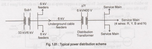
Power
receive at a 33 kV substation is first stepped down to 6 kV and with the help
of under ground cables (called feeder lines), power flow is directed to
different directions of the city. At the last level, step down transformers are
used to step down the voltage form 6 kV to 400 V. These transformers are called
distribution transformers with 400 V, star connected secondary. You must have
noticed such transformers mounted on poles in cities beside the roads. These
are called pole mounted substations. From the secondary of these transformers 4
terminals (R, Y, B and N) come out. N is called the neutral and taken out from
the common point of star connected secondary. Voltage between any two phases
(i.e., R-Y, Y-B and B-R) is 400 V and between any phase and neutral is 230 V (=
400 √3). Residential buildings are supplied with single phase 230V, 50Hz. So
individual are to be supplied with any one of the phases and neutral. Supply
authority tries to see that the loads remain evenly balanced among the phases
as far as possible. Which means roughly one third of the consumers will be
supplied from R-N, next one third from Y-N and the remaining one third from
B-N. The distribution of power from the pole mounted substation can be done
either by (1) over headlines (bare conductors) or by (2) underground cables.
Use of overhead lines a though cheap, is often accident prone and also theft of
power by hooking from the line stake place. Although costly, in big cities and
thickly populated areas underground cables for distribution of power, are used.
Basic Electrical, Electronics And Instrumentation Engineering: UNIT I: Electrical Circuits : Tag: : - Transmission And Distribution Of Electrical Energy
Basic Electrical, Electronics And Instrumentation Engineering: UNIT I: Electrical Circuits
Under Subject

Basic Electrical, Electronics and Instrumentation Engineering
BE3252 2021 Regulation | 2nd Semester Civil Dept 2021 Regulation
Related Subjects

Professional English II
HS3251 2nd Semester 2021 Regulation | 2nd Semester Common to all Dept 2021 Regulation

Statistics and Numerical Methods
MA3251 2nd Semester 2021 Regulation M2 Engineering Mathematics 2 | 2nd Semester Common to all Dept 2021 Regulation

Engineering Graphics
GE3251 eg 2nd semester | 2021 Regulation | 2nd Semester Common to all Dept 2021 Regulation

Physics for Electrical Engineering
PH3202 2nd Semester 2021 Regulation | 2nd Semester EEE Dept 2021 Regulation

Basic Civil and Mechanical Engineering
BE3255 2nd Semester 2021 Regulation | 2nd Semester EEE Dept 2021 Regulation

Electric Circuit Analysis
EE3251 2nd Semester 2021 Regulation | 2nd Semester EEE Dept 2021 Regulation

Physics for Electronics Engineering
PH3254 - Physics II - 2nd Semester - ECE Department - 2021 Regulation | 2nd Semester ECE Dept 2021 Regulation

Electrical and Instrumentation Engineering
BE3254 - 2nd Semester - ECE Dept - 2021 Regulation | 2nd Semester ECE Dept 2021 Regulation

Circuit Analysis
EC3251 - 2nd Semester - ECE Dept - 2021 Regulation | 2nd Semester ECE Dept 2021 Regulation

Materials Science
PH3251 2nd semester Mechanical Dept | 2021 Regulation | 2nd Semester Mechanical Dept 2021 Regulation

Basic Electrical and Electronics Engineering
BE3251 2nd semester Mechanical Dept | 2021 Regulation | 2nd Semester Mechanical Dept 2021 Regulation

Physics for Civil Engineering
PH3201 2021 Regulation | 2nd Semester Civil Dept 2021 Regulation
Basic Electrical, Electronics and Instrumentation Engineering
BE3252 2021 Regulation | 2nd Semester Civil Dept 2021 Regulation

Physics for Information Science
PH3256 2nd Semester CSE Dept | 2021 Regulation | 2nd Semester CSE Dept 2021 Regulation

Basic Electrical and Electronics Engineering
BE3251 2nd Semester CSE Dept 2021 | Regulation | 2nd Semester CSE Dept 2021 Regulation

Programming in C
CS3251 2nd Semester CSE Dept 2021 | Regulation | 2nd Semester CSE Dept 2021 Regulation