Basic Electrical, Electronics And Instrumentation Engineering: UNIT I: Electrical Circuits
Series And Parallel Circuit Analysis With Resistive, Capacitive And Inductive Network
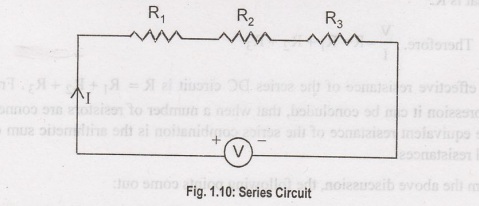
When all the resistive components ents of a DC circuit are connected end to end to form a single path for flowing current, then the circuit is referred as series DC circuit. The manner of connecting components end to end is known as series connection.
SERIES
AND PARALLEL CIRCUIT ANALYSIS WITH RESISTIVE, CAPACITIVE AND INDUCTIVE NETWORK
Series DC Circuit
When
all the resistive components ents of a DC circuit are connected end to end to
form a single path for flowing current, then the circuit is referred as series
DC circuit. The manner of connecting components end to end is known as series
connection. Suppose we have n number of resistors R1, R2,
R3, ..., Ra and they are connected in end to end manner,
means they are series connected. If this series combination is connected across
a voltage source, end current starts flowing through that series combination is
connected across a voltage source, the current starts flowing through that
single path. As the resistors are connected in end to end manner, the current
first enters in to R,, then this same current comes in R2, then R, and at last
it reaches R,, from which the current enters into the negative terminals of the
voltage source. In this way, the same current circulates through every resistor
connected in series. Hence, it can be concluded that in a series DC circuit,
the same current flows through all parts of the electrical circuit. Again
according to Ohm's law, the voltage drop across a resistor is the product of
its electrical resistance and the current flow through it. Here, current
through every resistor is the same, hence the voltage drop across each
resistor's proportional to its electrical resistance value. If the resistances
of the resistors are not equal then the voltage dro across them would also not
be equal. Thus, every resistor has its individual voltage rop in a series DC
circuit.
An Example of Series in DC Circuit
Suppose
three resistors R1, R, and R, are connected in series across a voltage source
of V (quantified as volts) are shown in the Figure 1.11. Let current I
(quantified as Ampere) flow through the series circuit. Now according to Ohm's
law,
Voltage
drop across resistor R1, V1 = IR1
Voltage
drop across resistor R2, V2 = IR2
Voltage
drop across resistor R3, V3 = IR3
Voltage
drop across whole series DC circuit,
Voltage
drop across resistor R1 + Voltage drop across resistor R2
+ Voltage drop across resistor R3
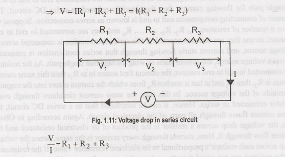
According
to Ohm's law, the electrical resistance of an electrical circuit is given by
V/I and that is R.
Therefore,
V/I =R=R1 + R2 + R3
So,
effective resistance of the series DC circuit is R=R1 + R2
+ R3. From the above expression it can be concluded, that when a
number of resistors are connected in series, the equivalent resistance of the
series combination is the arithmetic sum of their individual resistances.
From
the above discussion, the following points come out:
1.
When a number of electrical components are connected in series, the same
current flows through all the components of the circuit.
2.
The applied voltage across a series circuit is equal to the sum total of
voltage drops across each components.
3.
The voltage drop across individual components is directly proportional to it s
resistance value.
Parallel DC Circuit
When
two or more electrical components are connected in a way that one end of each
component is connected to a common point and the other end is connected to
another common point, then the electrical components are said to be connected
in parallel, and such an electrical DC circuit is referred as a parallel DC
circuit. In this circuit every component will have the same voltage drop across
them, and it will be exactly equal to the voltage which occurs between the two
drop across them, and it will be exactly equal to the voltage which occurs
between the two common points where the components are connected. Also in a
parallel DC circuit, the current has several parallel paths through these
parallel connected components, so the circuit current will be divided into as
many paths as the number of components. Here, in this electrical circuit, the
voltage drop across each component is equal. Again as per Ohm's law, voltage
drop across any resistive component is equal to the product of its electrical
resistance an current through it. As the voltage drop across every component
connected in parallel is the same, the current through them is inversely
proportional to its resistance value.
An Example of Parallel DC Circuit
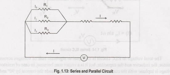
Suppose three resistors R., R., and R. are connected in parallel across R1, R2 and R, are connected in parallel across a voltage source of V (volt) as shown in the Figure 1.13. Let I (Ampere) be the total circuts current which is divided into current I, I, and I, flowing through R1, R2 and R, respectively. Now according to Ohm's law:
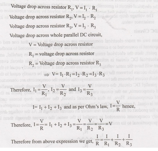
Thus
when a number of resistors are connected in parallel, the reciprocal of the
equivalent resistance is given by the arithmetic sum of the reciprocals of
their individual resistances. From the above discussion of the parallel DC
circuit, we can come to the following conclusion:
1.
Voltage drops are the same across all the components connected in parallel.
2.
Current through individual components connected in parallel, is inversely
proportional to their resistances.
3.
Total circuit current is the arithmetic sum of the currents passing through
individual components connected in parallel.
4.
The reciprocal of equivalent resistance is equal to the sum of the reciprocalss
the resistances of individuals components connected in parallel.
Series and Parallel Circuit
So
far we have discussed series DC circuit and parallel DC circuit separately, but
in practice, the electrical circuit is generally a combination of both series
circuits and parallel circuits. Such combined series and parallel circuits can
be solved by proper application of Ohm's law and the rules for series and
parallel circuits to the various parts of the complex circuit.
In
RLC circuit, the most fundamental elements like resistor, inductor and
capacitor are connected across a voltage supply. All these elements are linear
and passive in nature; i.e., they consume energy rather than producing it and
these elements have a linear relationship between voltage and current. There
are number of ways of connecting these elements across voltage supply, but the
most common method is to connect these elements either in series or in
parallel. The RLC circuit exhibits the property of resonance in same way as LC
circuit exhibits, but in this circuit the oscillation dies out quickly as
compared to LC circuit due to the presence of resistor in the circuit.
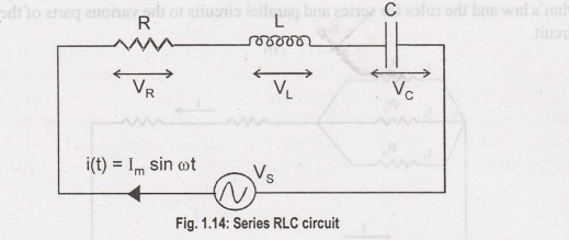
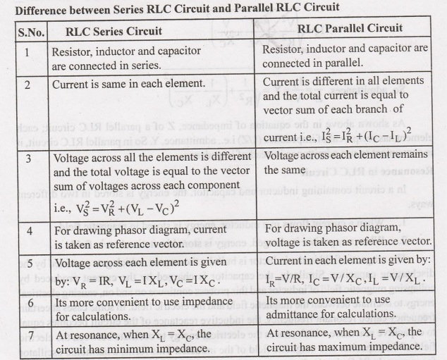
Series RLC Circuit
When
a resistor, inductor and capacitor are connected in series with the voltage
supply, the circuit so formed is called series RLC circuit. Since all these
components are connected in series, the current in each element remains the
same.
IR
= IL = IC = I(t) where I(t)= IM sin ωt
Let
VR be the votlage across resistor, R.
VL
be the voltage across inductor, L.
VC
be the voltage across capacitor, C.
XL
be the inductive reactance.
XC
be the capacitive reactance.
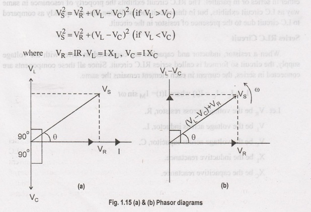
The
total voltage in RLC circuit is not equal to algebraic sum of voltages across
the resistor, the inductor and the capacitor, but it is a vector sum because,
in case of resistor the voltage is inphase with the current, for inductor the
voltage leads the current by 90° and for capacitor, the voltage lags behind the
current by 90°. So, voltages in each component are not in phae with each other;
so they cannot be added arithmetically. The figure below shows the phasor
diagram of series RLC circuit. For drawing the phasor diagram for RLC series
circuit, the current is taken as reference because, in series circuit the
current in each element remains the same and the corresponding voltage vectors
for each component are drawn in reference to common current vector.
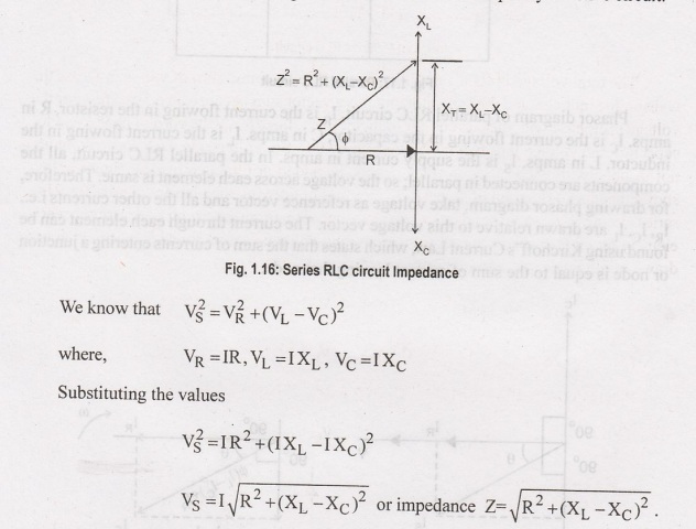
The Impedance for a Series RLC
Circuit
The
impedance Z of a series RLC circuit is defined as opposition to the flow of
current due circuit resistance R, inductive reactance, X, and capacitive
reactance, X. If the inductive reactance is greater than the capacitive
reactance i.e., X1 > Xc, then the RLC circuit has lagging phase angle and if
the capacitive reactance is greater than the inductive reactance i.e., XXL
then, the RLC circuit have leading phase angle and if both inductive and
capacitive are same. i.e., X = Xc then circuit will behave as purely resistive
circuit.
Parallel RLC Circuit
In
parallel RLC Circuit the resistor, inductor and capacitor are connected in
parallel across a voltage supply. The parallel RLC circuit is exactly opposite
to the series RLC circuit. The applied voltage remains the same across all
components and the supply current gets divided. The total current drawn from
the supply is not equal to mathematical sum of the current flowing in the
individual component, but it is equal to its vector sum of all the currents, as
the current flowing in resistor, inductor and capacitor are not in the same
phase with each other; so they cannot be added arithmetically.
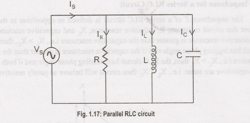
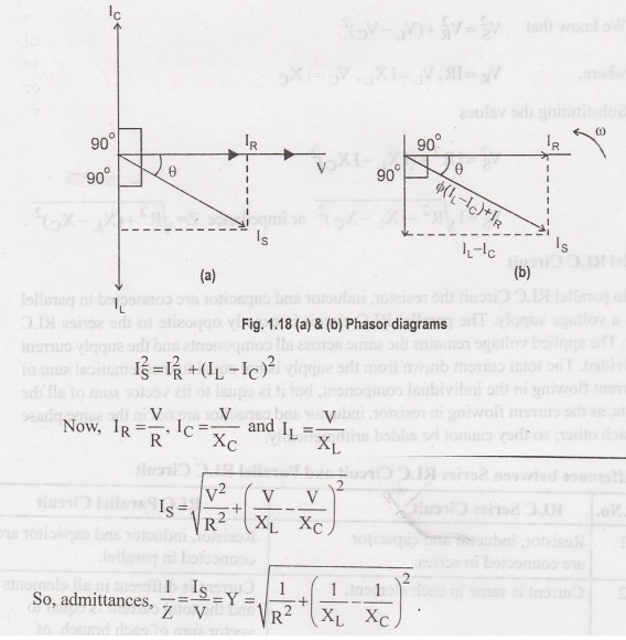
Phasor
diagram of parallel RLC circuit, I, is the current flowing in the resistor, R
in amps. I is the current flowing in the capacitor, C in amps. It is the
current flowing in the inductor, L in amps. I, is the supply current in amps.
In the parallel RLC circuit, all the components are connected in parallel; so
the voltage across each element is same. Therefore, for drawing phasor diagram,
take voltage as reference vector and all the other currents i.e., IR, IC. I are
drawn relative to this voltage vector. The current through each element can be
found using Kirchoff's Current Law, which states that the sum of currents
entering a junction or node is equal to the sum of current leaving that node.
As
shown above in the equation of impedance, Z of a parallel RLC circuit; each
element has reciprocal of impedance (1/Z) i.e., admittance, Y. So in parallel
RLC circuit, it is convenient to use admittance instead of impedance. mols ont
le
Resonance in RLC Circuit
In
a circuit containing inductor and capacitor, the energy is stored in two
different
1.
When a current flows in a inductor, energy is stored in magnetic field.
2.
When a capacitor is charged, energy is stored in static electric field.
The
magnetic field in the inductor is built by the current, which gets provided by
the discharging capacitor. Similarly, the capacitor is charged by the current
produced by collapsing magnetic field of inductor and this process continues on
and on, causing electrical energy to oscillate between the magnetic field and
the electric field. In some cases at certain frequency called resonant
frequency, the inductive reactance of the circuit becomes equal to capacitive
reactance which causes the electrical energy to oscillate between the electric
field of the capacitor and magnetic field of the inductor. This forms a
harmonic oscillator for current. In RLC circuit, the presence of resistor
causes these oscillations to die out over period of time an it is called as the
damping effect of resistor.
Formula for Resonant Frequency
During
resonance, at certain frequency called resonant frequency, f.
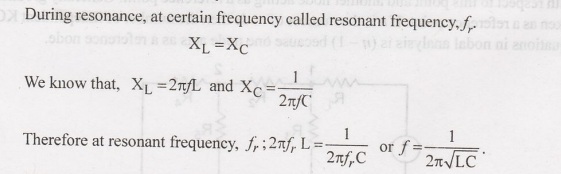
When
resonance occurs, the inductive reactance of the circuit become equal to
capacitive reactance, which causes the circuit impedance to be minimum in case
of series RLC circuit; but then resistor, inductor and capacitor are connected
in parallel, the circuit impedance becomes maximum, so the parallel RLC circuit
is sometimes called as anit resonator.
Basic Electrical, Electronics And Instrumentation Engineering: UNIT I: Electrical Circuits : Tag: : - Series And Parallel Circuit Analysis With Resistive, Capacitive And Inductive Network
Related Topics
Related Subjects

Basic Electrical, Electronics and Instrumentation Engineering
BE3252 2021 Regulation | 2nd Semester Civil Dept 2021 Regulation