Basic Electrical, Electronics And Instrumentation Engineering: UNIT I: Electrical Circuits
Mesh Analysis
Steps for Solving Mesh Equation
Mesh analysis is a method that is used to solve planar circuits for the current at any place in the circuit. Planar circuits are that can be drawn on a plane surface with no wires crossing each other.
MESH
ANALYSIS
Mesh
analysis is a method that is used to solve planar circuits for the current at
any place in the circuit. Planar circuits are that can be drawn on a plane
surface with no wires crossing each other. It is also called as loop analysis.
Generally KVL and KCL are used in deriving the mesh and nodal equations
respectively.
Mesh
equations are desired from the division of current in these meshes. A loop
current is different from branch current. In order to illustrate this
difference, consider the circuit shown in Figure 1.19(a).

The
given circuit is redrawn with nodes as shown in Figure 1.20(b). Here we can
identify two closed loops or meshes represented as mesh 1 (abda) and mesh '2'
(bcdb). Here I1, and I2are the mesh currents flowing in
mesh '1' and mesh '2' respectively,

As
the branch 'bd' consisting of resistor, R, is shared between the meshes 1 and
2, the resultant branch current is I,. The magnitude of I, depends on the
magnitudes of both the mesh currents I, and I, from the circuit shown in Figure
1.11(b) the current directions I, and I, in R, are opposite to each other.
Hence

The
possible way of drawing one more closed path through the elements
V1
→ R1 → R2 →V2 and→ V1 is shown in
Figure 1.11(c).
Assigning
the direction of mesh current is arbitrary. In order to simplify the procedure
for writing the mesh equation, the preferred direction for the flow of current
is usually clockwise.

If
an element is located on the boundary between two meshes such as R, in figure
1.11(d) the element current is the algebraic sum of the currents flowing
through it.
Steps for Solving Mesh Equation
Step 1:
Ensure that the circuit has only voltage sources. If there is current source
convert it into the voltage source first.
Step 2:
Assume the direction of current in advance.
Step 3:
Mark the polarities of voltage drops across each element.
Step 4:
Assign correct polarity to the voltage source.
Step 5:
Write the mesh equation using KVL and equate the algebraic sum of voltage drops
to zero in that particular mesh.
Step 6:
For the shared branch the algebric sum of mesh currents flowing through it is
considered.
Step 7:
Solve the mesh equations to find the solution for unknown quantities.
Example 1.14:
Write the mesh equations for the circuit shown below and determine the

Example 1.15:
Determine the loop currents of the circuit shown in figure below. Also find the
current through 6ῼ resistor.
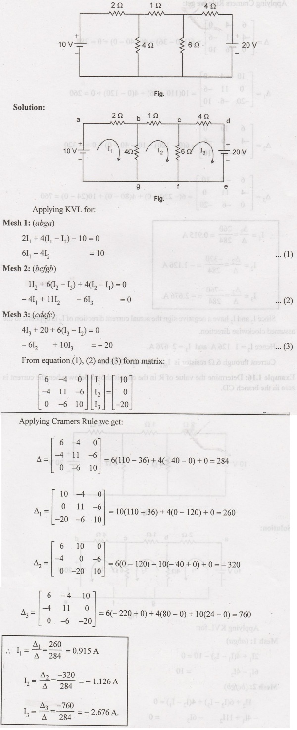
Since
I2 and I3 have a negative sign the actual current
direction of I2 is opposite to the assumed clockwise direction.
Hence
I2 = 1 126 A and I3 = 2 676 A.
Current
through 6. Q resistor is 16ῼ = 13 — I2 = 1.55 A.
Example 1.16:
Determine the value of R in the circuit shown below when the current is zero in
the branch CD.
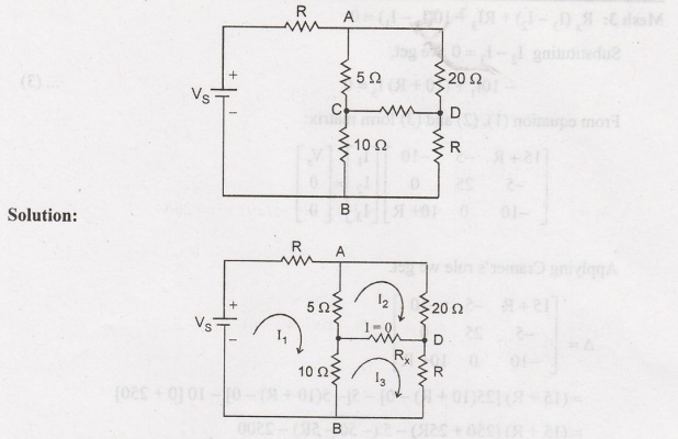
Assuming
current direction to be clockwise.
Applying
KVL for
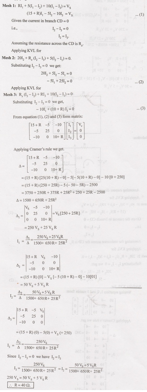
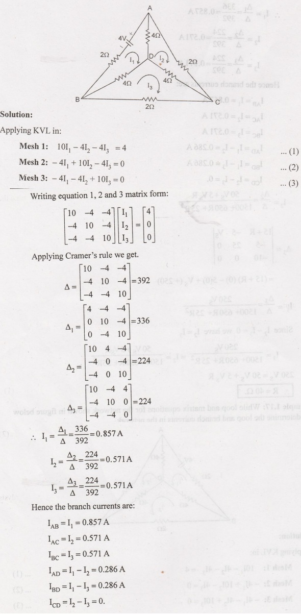
Example 1.17:
While loop and matrix equations for the network shown in figure below and
determine the loop and branch currents in the network.
Example 1.18:
Write the mesh equation for the circuit shown below and determine the current
in each loop.
Solution:
From
the circuit the mesh 1 consists of outer parameter current is I1 =
25 A.

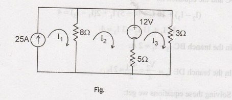
Example 1.19:
For the given circuit find the voltage across 5 2 resistor using mesh analysis method.
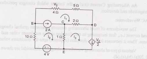
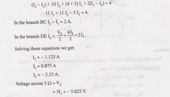
As
the branches BC and DE consist of current sources, we can form a super CEBDC
and the equation is:
Basic Electrical, Electronics And Instrumentation Engineering: UNIT I: Electrical Circuits : Tag: : Steps for Solving Mesh Equation - Mesh Analysis
Related Topics
Related Subjects

Basic Electrical, Electronics and Instrumentation Engineering
BE3252 2021 Regulation | 2nd Semester Civil Dept 2021 Regulation