Basic Electrical, Electronics And Instrumentation Engineering: UNIT I: Electrical Circuits
Kirchoff's Law
Kirchoff's current and voltage laws are used to systematically analyze the relationships between voltages and currents in a given electric circuit.
KIRCHOFF'S
LAW
Kirchoff's
current and voltage laws are used to systematically analyze the relationships
between voltages and currents in a given electric circuit.
Kirchoff's Current Law
(KCL)
Kirchoff's
current law states that the algebraic sum of currents at any node is zero. That
is the total current entering a node is equal to the total current leaving that
node.
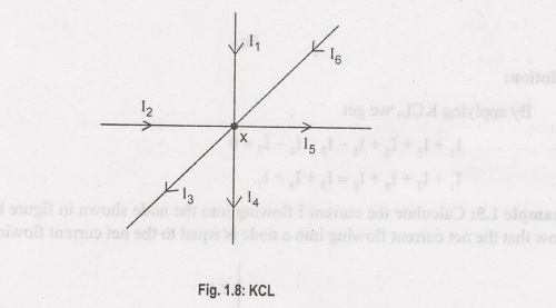
From
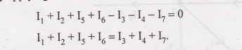
Figure 1.8. There are three positive currents I, I, and I and three negative
currents 13, 14, 15. Then according to Kirchoff's current law, The algebraic
sum of the currents should be equal to zero.
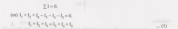
If
it is assumed that current entering the node has negative polarity and current
leaving the node has positive polarity then KCL is written as:
Equation
(1) and (2) are same is both the cases.
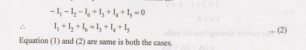
Example 1.4:
Write the equation for the current at the node shown in the figure below
Solution:
By
applying KCL, we get
Example
1.5: Calculate the current I flowing into the node shown in figure below. Also
show that the net current flowing into a node is equal to the net current
flowing out of it,
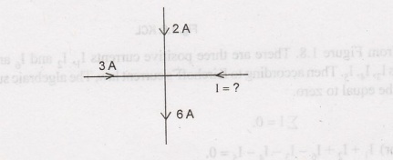
Solution:
Consider
the current flowing toward the node as positive currents and leaving the nodes
as negative currents. Applying KCL we get
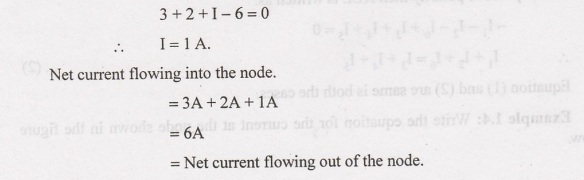
Example 1.6:
For the circuit shown below calculate the value of current
Two
separate nodes 'a' and 'b' can be merged into a single super node c is shown in
figure below.
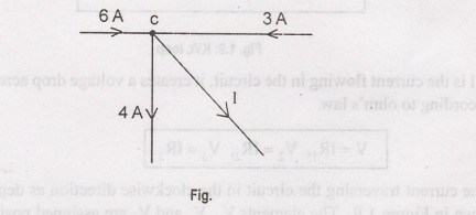
Applying
KCL to super-node 'c' we get
6-3=4+I.
Therefore
I = -1 A.
The
negative sign in the result shows that the actual direction of the flow of
current I is opposite to the direction of flow of current as shown in figure.
Kirchoff's Voltage Law
(KVL)
KVL
states that the algebraic sum of voltages or voltage drops in any closed path
of network that is traversed in a single direction is zero i.e., in a closed
path, mesh or loop Σν = 0.
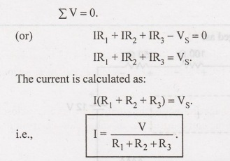
Hence
the algebraic sum of the voltage drop across the circuit elements of any closed
path in a circuit is equal to the sum of the emf's or sources of voltages in
that path i.e., ΣIR = ΣV.
From
the Figure 1.9. Let us consider a single loop circuit. Here the traversal has
started from node 'a' and then nodes 'b' and 'c' and 'd' along a clockwise
direction and ended at the same node 'a'.
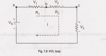
If
I is the current flowing in the circuit, it creates a voltage drop across each
resistor. Then according to ohm's law.
V=IR1,
V2 = IR2, V3 = IR3.
The
current traversing the circuit in the clockwise direction as depicted by dashed
line shown in Figure 1.9. The elements V1,
V2 and V3 are assigned positive sign and its positive a
polarity is met first in the assumed traverse direction. Similarly Vs is
assigned negative sign as its negative terminal is met first in the assumed
traverse direction. The starting point of the loop is entirely arbitrary but it
must start and end at the same point.
By
applying KVL through the direction a -b -c -d - a we get
V1+V2+V3
- Vs=0
Example 1.7:
Determine the value of unknown voltage drop VR for the circuit shown below:
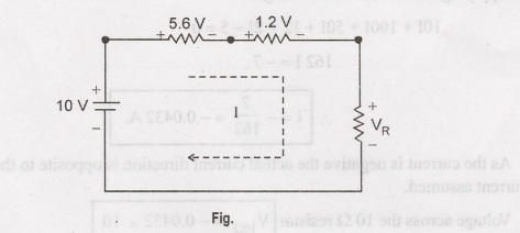
Solution:
Applying
KVL we get
5.6+1.2+VR
- 10 = 0
VR
= 3.2 V.
Example 1.8:
For the circuit shown below find the circuit current and voltage across the 10
Ω resistor.
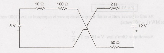
Solution: The
circuit can be re-arranged as:
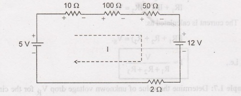
Applying
KVL to the circuit we get:
101
+1001+501 + 12+ 21-5=0.3
162
I=-7
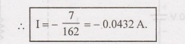
As
the current is negative the actual current direction is opposite to the
direction of the current assumed.
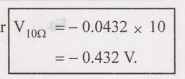
Voltage
across the 10 2 resistor
Basic Electrical, Electronics And Instrumentation Engineering: UNIT I: Electrical Circuits : Tag: : - Kirchoff's Law
Related Topics
Related Subjects

Basic Electrical, Electronics and Instrumentation Engineering
BE3252 2021 Regulation | 2nd Semester Civil Dept 2021 Regulation