Basic Electrical, Electronics And Instrumentation Engineering: UNIT I: Electrical Circuits
Generation Of AC Voltage
The machines which are used to generate electrical voltages are called generators. The generators which generate pure sinusoidal a.c voltage waveforms are called as alternators.
GENERATION
OF AC VOLTAGE
The
machines which are used to generate electrical voltages are called generators.
The generators which generate pure sinusoidal a.c voltage waveforms are called
as alternators.
The
basic principle of an alternator is the principle of electromagnetic induction.
The sine wave is generated according to Faraday's law of electromagnetic
induction.
Emf induced for different
situations:
(i) Moving the conductor across the
lines of force.
In
this case maximum flux lines will be cuts by the conductor.
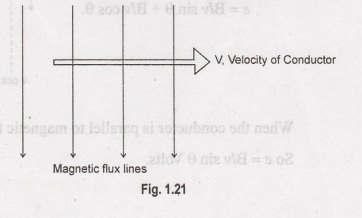
where
e
→ induced emf (v)
B→
flux density (ob/m2)
1
→ length of conductor (m)
v
→ velocity of conductor (m/sec).
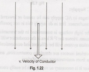
(ii) Moving the conductor parallel
to the lines of force.
In
this case, no flux lines will cut the conductor.
So
e = 0 v.
(iii) Moving the conductor in such
a way making an angle 'θ' with the lines of force.
In
this case, velocity (v) can be resolved into two components.
(i) Across the magnetic
flux
= v sin θ
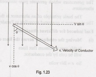
When
the conductor is parallel to magnetic flux line e = 0.
So
e = Blv sin 0 Volts.
Equation of an Alternating Quantity
To
derive the equation of an ac quantity, consider single turn, 2 pole alternator.
Th coil is rotated with constant angular velocity in the magnetic fields.
An
alternating emf induced is purely sinusoidal in nature.
Let
B → Flux density of the magnetic field in ob/m2
1
→ Active length of each conductor in metres
r→
Radius of circular path traced by conductors in metres
ω→
Angular velocity of coil in radians/second
v
→ Linear velocity of conductor in m/sec.
Now
v=rω.
Consider
an instant where coil has rotated through angle corresponding to θ=θ° i.e.,
from the instant when induced emf is zero.
If
requires time 't' to rotate through 0. So e in radians can be expressed as: 0 =
θ=
wt radians.
The
position of coil is shown in Figure 1.24(a). The instantaneous peripheral
velocity of any conductor can be resolved into two components as shown in
Figure 1.24(b).
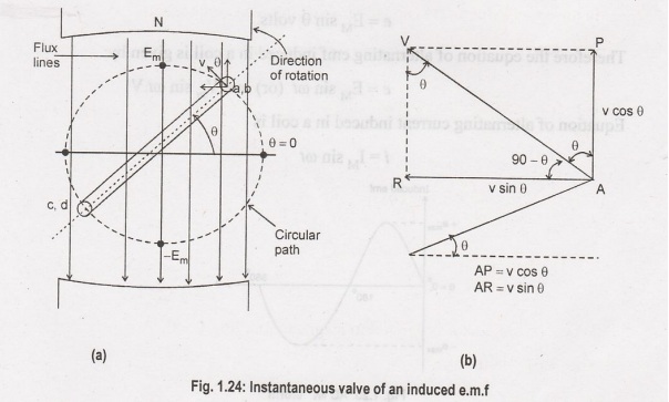
The
components of velocity, vare:
(1)
Parallel to the magnetic flux lines
(2)
Perpendicular to the magnetic flux lines = v sin θ.
Out
of the two, due to the component parallel to the flux, the component parallel
to the flux, there cannot be the gene of the e.m.f as there cannot be the
cutting of the flux lines. Hence the component which is acting perpendicular to
the magnetic flux lines.
According
to the Faraday's law electromagnetic induction, the expression for the generated emf in each conductor is:
The
active length 'l' means the length of the conductor which is under the
influence of the magnetic field.
Now
Em = Blv
=
maximum valve of induced emf in conductor.
This
is achieved at θ = 90° and is the peak value or amplitude of the sinusoidal
induced emf.
Hence
the equation giving instantaneous valve of the generated e.m.f can be expressed
as
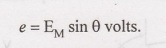
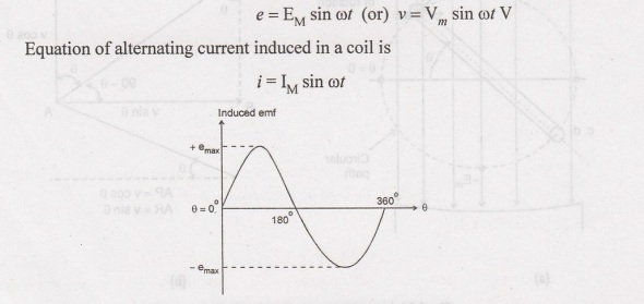
Therefore
the equation of alternating emf induced in a coil is given by:
Basic Electrical, Electronics And Instrumentation Engineering: UNIT I: Electrical Circuits : Tag: : - Generation Of AC Voltage
Related Topics
Related Subjects

Basic Electrical, Electronics and Instrumentation Engineering
BE3252 2021 Regulation | 2nd Semester Civil Dept 2021 Regulation