Physics For Civil Engineering: Unit I: Thermal Application
Conduction of Heat Through Compound Media
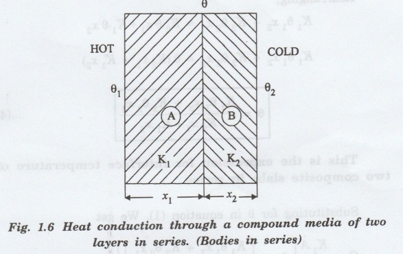
Let us consider a compound media of two different materials A and B with thermal conductivities K1 and K2 and thicknesses x1 and x2
CONDUCTION OF HEAT THROUGH COMPOUND MEDIA
Material
bars in series
Let us consider a compound media of two
different materials A and B with thermal conductivities K1 and K2
and thicknesses x1 and x2 (fig. 1.6).
After the steady state is reached,
Amount of heat flowing through the
material (A) per second
Q = KA (θ1 – θ)
t / x
1 ………………….(1)
Amount of heat flowing through the
material (B) per second
Q = KA (θ – θ2)
t / x2 …………………….(2)
The amount of heat flowing through the
materials A and B is equal in steady state conditions.
Hence, the eqns (1) & (2) are equal
K1A (θ1
– θ) t / x 1 = K2A (θ
– θ2) t / x2 …………….(3)
Rearranging the eqn (3), we have

Rearranging,
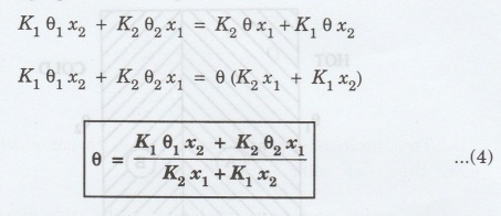
This
is the expression for interface temperature of two composite slabs in series.
Substituting for θ in equation (1), We
get
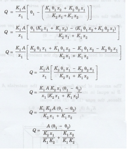
The amount of heat flowing per second through compound wall of two materials.

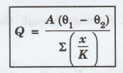
This method can also be extended to
composite slab with more than two slabs.
In general for any number of slabs, the
amount of heat conducted per sec is given by
Materials
in parallel
Consider a composite media of two
different materials A and B with thermal conductivities K1 and K2
and thicknesses x1 and x2. They are arranged in parallel
as shown in fig. 1.7.
The faces of the material A and B are at
temperature e, and the other end faces of A and B are at temperature θ2.
A1 and A2 are the are of cross-section of the materials.
Amount of heat flowing through the first
material (A) in one second.
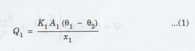
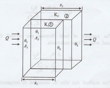
Fig.
1.7 Heat conduction through the bodies in parallel
Similarly
Amount of heat flowing through the
second material (B) in one second.
Q2 = K2 A2
(θ1-θ2) / x2………………..(2)
The total heat flowing through these
materials per second and is equal to the sum of Q1 and Q2
Q
= Q1 + Q2
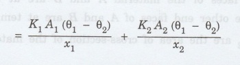
∴ Amount
of heat flowing per second
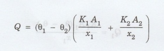
In general, the net amount of heat
flowing per second parallel to the composite slabs is given by
Q = (θ1
- θ2) Σ KA/ x
Note:
This expression is valid where the heat is conducted
through various materials simultaneously under temperature condition.
Problem
1.4
A cooper rod of length 50cm and
cross-sectional area 6 x 10⁻² cm 2 is connected in sereis
with an iron rod of same area of cross-section and length 25 cm. One end of
copper is immersed in boiling water. The far end of the iron is in an ice bath
of 0°C. Find the rate of transfer of heat from boiling water to ice bath.
(Thermal conductivity of copper and iron are 401 Wm-1 K-1
and 80 Wm-1 K-1 respectively.)
Given
Length of copper rod x1 = 50cm
= 50 x10-2 cm
Length of the iron rod x2 = 25cm
= 25 x10-2 cm
Temperature of ice bath θ2 =
0oC
Temperature of boiling water θ1 = 100oC
Thermal conductivity of copper
K1 = 401 Wm -1K-1
Thermal conductivity of iron
K2 = 80 Wm -1K-1
Area of cross section of Copper and Iron
= 6 × 10⁻² cm2
= 6 x 10-2 x (10-2
m)2
= 6 x 10-2 x 10-4
m2
Solution:
The rods are connected in series.
Therefore, the rate of heat flow from boiling end to ice

Methods
to determine thermal Conductivity
The thermal conductivity of a material
is determined by various methods
1. Searle's method for good conductors
like metallic rods
2. Forbe's method for determining the
absolute conductivity of metals.
3. Lee's disc method for bad conductors
4. Radial flow method for bad
conductors.
Radial
flow method
This is interesting because there is no loss
of heat as in the case of other methods. In this method heat will flow from the
inner side towards the other side along the radius of the spherical shell and
cylindrical shell.
Spherical method is suitable for poor
conductors available in powder form, like asbestos, cork, charcoal, clay, sand,
etc. In the cylindrical shell method, the thermal conductivity of a thick
walled glass tube or rubber tube can be determined by allowing heat to flow
radially through the walls of the tube.
Spherical
shell method
The material to which, thermal
conductivity K has to be found is placed between two thin spherical shells A
and B of r1 radii and r2 as shown in figure 1.8.
A source of constant heat supply is
fixed at the centre of the shells. Heat flows radially across the wall of the
shell from inner to outer side. The heat is passed through the material and
subsequently lost by emission from the surface of the outer shell.

After a steady state is reached let the
temperature of the inner and the outer shells be θ1 and θ2.
Imagine spherical surfaces at a distance
r and r + dr from O at temperature θ and θ +d θ.
The rate of flow of heat across this
shell per second

This quantity of heat is equal to the
energy supplied by the source at the centre per second.
Rearranging
We have dr / r2 = -4 Πk/Q
dθ…………………..(2)
Q is constant for the values of r as a
steady state has reached.
Integrating (2) between the limits r1
and r2 and the corresponding temperatures θ1 and θ2.

Cylindrical
shell method
This is similar to the spherical shell
method.
Consider a cylindrical tube of length l,
inner radius r1 and outer radius r2 as shown in fig. 1.9.
The tube carries steam or some hot liquid.
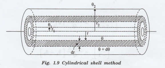
Heat is conducted radially across the
walls of the tube. After the steady state is reached, the temperature on the
inner surface is θ1 and on the outer surface is θ 2.
This thick pipe is imagined to consist
of a large number of thin co-axial cylinders of increasing radius. Any such
thin imaginary cylinder of the material of thickness 'dr' at a distance r from
the axis of the pipe is taken.
Amount of heat flowing per second
through this elementary cylinder
Q = - KA dθ / dr …………….. (1)
Now, surface area of the imaginary
cylinder
A = 2π r x l
∴ Q = -2
π r Lk dθ / dr ………….(2)
After
steady state is reached, the amount of heat flowing (Q) through all the
imaginary cylinders is same.
Re-arranging the equation (2), we get
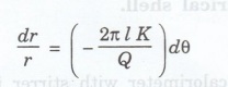
Integrating both sides between their
proper limits, we have

Physics For Civil Engineering: Unit I: Thermal Application : Tag: : - Conduction of Heat Through Compound Media
Physics For Civil Engineering: Unit I: Thermal Application
Under Subject

Physics for Civil Engineering
PH3201 2021 Regulation | 2nd Semester Civil Dept 2021 Regulation
Related Subjects

Professional English II
HS3251 2nd Semester 2021 Regulation | 2nd Semester Common to all Dept 2021 Regulation

Statistics and Numerical Methods
MA3251 2nd Semester 2021 Regulation M2 Engineering Mathematics 2 | 2nd Semester Common to all Dept 2021 Regulation

Engineering Graphics
GE3251 eg 2nd semester | 2021 Regulation | 2nd Semester Common to all Dept 2021 Regulation

Physics for Electrical Engineering
PH3202 2nd Semester 2021 Regulation | 2nd Semester EEE Dept 2021 Regulation

Basic Civil and Mechanical Engineering
BE3255 2nd Semester 2021 Regulation | 2nd Semester EEE Dept 2021 Regulation

Electric Circuit Analysis
EE3251 2nd Semester 2021 Regulation | 2nd Semester EEE Dept 2021 Regulation

Physics for Electronics Engineering
PH3254 - Physics II - 2nd Semester - ECE Department - 2021 Regulation | 2nd Semester ECE Dept 2021 Regulation

Electrical and Instrumentation Engineering
BE3254 - 2nd Semester - ECE Dept - 2021 Regulation | 2nd Semester ECE Dept 2021 Regulation

Circuit Analysis
EC3251 - 2nd Semester - ECE Dept - 2021 Regulation | 2nd Semester ECE Dept 2021 Regulation

Materials Science
PH3251 2nd semester Mechanical Dept | 2021 Regulation | 2nd Semester Mechanical Dept 2021 Regulation

Basic Electrical and Electronics Engineering
BE3251 2nd semester Mechanical Dept | 2021 Regulation | 2nd Semester Mechanical Dept 2021 Regulation
Physics for Civil Engineering
PH3201 2021 Regulation | 2nd Semester Civil Dept 2021 Regulation

Basic Electrical, Electronics and Instrumentation Engineering
BE3252 2021 Regulation | 2nd Semester Civil Dept 2021 Regulation

Physics for Information Science
PH3256 2nd Semester CSE Dept | 2021 Regulation | 2nd Semester CSE Dept 2021 Regulation

Basic Electrical and Electronics Engineering
BE3251 2nd Semester CSE Dept 2021 | Regulation | 2nd Semester CSE Dept 2021 Regulation

Programming in C
CS3251 2nd Semester CSE Dept 2021 | Regulation | 2nd Semester CSE Dept 2021 Regulation