Water Supply And Wastewater Engineering: Unit III: Water Storage And Distribution
Analysis of Water Distribution Systems
with Solved Example Problems
The Algebraic sum of pressure drops around a closed loop must be zero. (i.e. no discountinuity in pressure),The flow entering a junction must be equal to the flow leaving the same junction. i.e. law of continuity must be satisfied.
ANALYSIS
OF DISTRIBUTION SYSTEMS
Conditions
to be satisfied in pipe networks:
•
The Algebraic sum of pressure drops around a closed loop must be zero. (i.e. no
discountinuity in pressure)
•
The flow entering a junction must be equal to the flow leaving the same
junction. i.e. law of continuity must be satisfied.
Pipe
networks are solved by the following methods:
(1)
Hardy - Cross Method
(2)
Equivalent Pipe Method
1. HARDY-CROSS METHOD
•
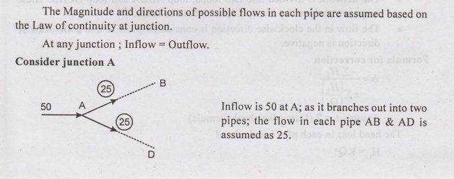
This method is based on the principle of "Law of Continuity". i.e. at
any junction, Inflow = Outflow
•
The flow in each pipe is assumed.
•
A correction to the assumed flow is computed successively for each pipe loop in
the network, until the correcton is reduced to an acceptable magnitude.
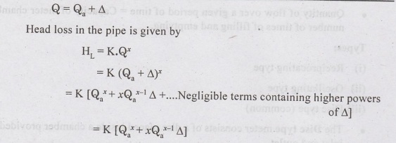
If
Q = assumed flow, Q = actual flow, then correction A is given by sub divendr
∆
= Q – Q

•
Algebraic sum of head losses in various pipes in closed loop is computed with
assumed flow.
•
Correction A is found for each loop
•
Assumed flows in each pipe are corrected.
•
Pipes common to two loops will receive both corrections with due attention to
sign.
The Procedure adopted in Hardy
Cross method is as follows:
•
The Distribution system is divided into 2 or more loops, such that each pipe in
network is included in atleast one loop.
•
Assume any internally consistent distribution of flow. The sum of flows
entering 02 2 bor any junction must be equal to the sum of flows leaving that
junction. no (INFLOW OUTFLOW)
•
Compute head loss in each pipe by equation or diagram. Conventionally,
clockwise flows are positive and vice versa.
•
With due attention to sign, compute total head loss around the circuit. EKQ2
•
Compute without regard to sign, for the circuit, the sum of 
•
Apply corrections obtained from Equation 1 and 2 to the flow in each pipe.
Pipes common to two loops will receive both corrections with due regard to
sign.
Problem 3.3:
Determine
the distribution of flow in the pipe network. The Head loss H1 may be assumed
as KQ". The flow is turbulent and pipes are rough. The Value of K for each
pipe is shown in figure. Use Hardy Cross method.
Solution:


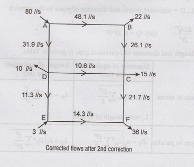
Problem 3.4:
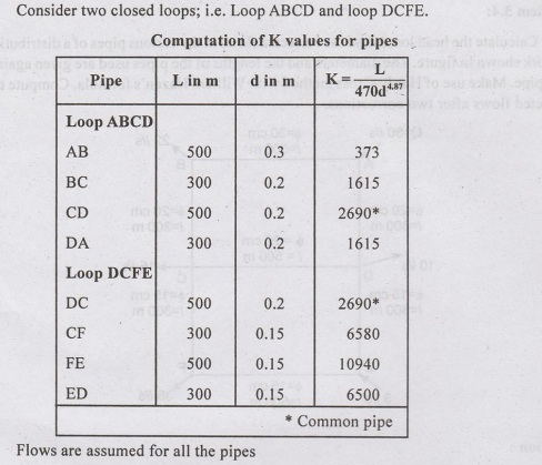
Calculate
the head losses and the corrected flows in the various pipes of a distribution
network shown in figure. The diameters and the lengths of the pipes used are
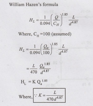
given against each pipe. Make use of Hardy-Cross method with William Hazen's
formula. Compute the corrected flows after two corrections.

Solution:


EQUIVALENT PIPE METHOD:
•
In this method, a complex network of pipes is replaced by a single
hydraulically equivalent pipe.
•
The equivalent pipe is one which will replace a system of pipes with equal head
loss for a given flow.

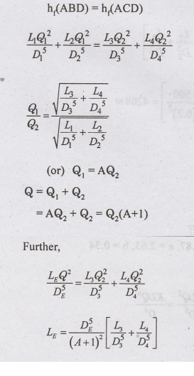
The two hydraulic principles used
in this method are :
(i)
The Head loss through the pipes connected in series (AB-BD) is additive.
(ii)
The flows (discharge) through the pipes connected in parallel (ABD-ACD) is
distributed such that the head losses are identical.
For
solving the pipe network, any head loss formula can be used.
Let
DE - Diameter of equivalent pipe
LE=Length
of equivalent pipe
L,
D = represent length and diameter of pipes in the network

Note:
For Hazen williams formula x = 4.87, a = 2.63, b = 0.54
For
the flow network shown in figure.

Pipes in Series
Length
of equivalent pipe for pipe AB and BD in series is given by:
Total
head loss = summation of individual head loss.

Pipes in parallel (pipes ABD and
ACD)
Problem 3.5
Find
the equivalent length of 30 cm dia pipe for the network shown in figure using
(a) Darcy's formula, (b) Hazen Williams formula.

Solution:
(a) Darcy's formula

(b) Hazen Williams formula

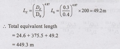
Problem 3.6:
Find
the equivalent length of 30 cm dia pipe for the network shown in Figure. Use
Hazen Williams formula.

Solution:
Using
Hazen Williams formula [x = 4.87, n=1.85]
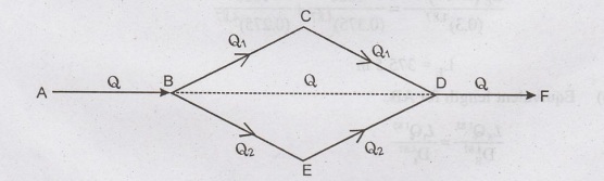
Let
the discharge in loop BCD be Q1 and BED be Q2
Q
= Q1 + Q2

(a) For the equivalent pipe BD,

(b) Equivalent length for AB,

(c) Equivalent length for DF,
Water Supply And Wastewater Engineering: Unit III: Water Storage And Distribution : Tag: : with Solved Example Problems - Analysis of Water Distribution Systems
Related Topics
Related Subjects

Water Supply and Wastewater Engineering
CE3303 3rd Semester Civil Dept 2021 Regulation | Tag: 3rd Semester Civil Dept 2021 Regulation