Water Supply And Wastewater Engineering: Unit V: Sewage Treatment And Disposal
Trickling Filters
Classification, Construction, Design | Sewage Treatment
It is an Aerobic and Attached Growth process (the microorganisms remain attached to the filter media),Trickling filters are also known as percolating filters (or) sprinkling filters.
TRICKLING
FILTERS
•
It is an Aerobic and Attached Growth process (the microorganisms remain
attached to the filter media).
•
Trickling filters are also known as percolating
filters (or) sprinkling filters.
•
Sewage is allowed to sprinkle (or)
trickle over a bed of coarse, rough, hard filter media and it is then collected
in the under-drainage system.
•
Spray nozzles (or) rotary distributors provided on top are used for sprinkling
sewage diwong on filler media.
• The
biological purification is brought about mainly by aerobic bacteria, which form
a bacterial film (biofilm) around particles of filter media.
• The color of this film is blackish, greenish
and yellowish and apart from bacteria it or may consist of fungi, algae,
protozoa, etc.

• Sufficient O2 (oxygen) is supplied inside
filter for the existence of this bio-film.
• Organics are removed by bisorption.
• The trickling filter is always preceded by
primary sedimentation tank along with the skimming devices to remove the scum.
This will prevent the clogging of the filter by settleable solids.
• The effluent from the filter is then taken
to secondary sedimentation tank for settling out organic solids oxidised while
passing through the filter.
•
The microbial film (or biofilm) (or) the slime film formed on the filter medium
is aerobic to a depth of only 0.1 to 0.2 mm, and the remaining part of the film
is anaerobic.
•
As the waste water flows over the microbial film, the soluble organic material
in the sewage is rapidly metabolished while the colloidal organics are adsorbed
onto the surface.
•
In the outer layer of the biological film, the organic matter is degraded by
the aerobic micro organisms. The food concentration and oxygen supply is high
at the outer layer, which leads to rapid growth of aerobic microbes and thereby
the thickness of slime layer increases.
•
The D.O. is therefore consumed at the upper layers itself and prevents its
penetration to lower zone. Hence the lower zone of the film is in starvation of
oxygen and food due to which anaerobic environment is established.
•
The micro-organisms in the lower zone therefore enter into endogeneous phase of
growth and lose their ability to stick to the media surface.
•
Eventually there will be scouring of the slime layer and new fresh slime layer
begins to grow again on the media.
•
This phenomenon of scouring of the slime layer is called sloughing.

Classification of Trickling
Filters:
(i)
Low Rate Trickling Filters (or) Standard Rate Trickling Filter (SRTF)
(ii)
High Rate Trickling Filters (HRTF).
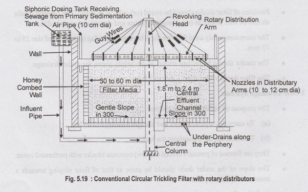
Construction of Conventional
Trickling Filters:
•
A trickling filter consists of:
(i)
A water tight holding tank made of masonry or concrete walls.
(ii)
Distribution system
(iii)
Filter media and
(iv)
Under-drainage system.
•
Tank is either square, rectangular or circular in shape.
•
Influent to the trickling filter is from the primary sedimentation tank.
Filter Media:
•
The filter media used should have high surface area, high void space,
resistance to abrasion and insoluble.
•
Particles of filter media should be round (or) cubical in shape. The filtering
media should be free from flat (or) elongated pieces and should not contain
dirt.
•
The most commonly used filter media is broken stone, slag (or) gravel of size
25 to 75 mm.
•
The media should be packed atleast 30 cm height above the under drainage.
•
The filter depth varies from 1.8 m to 3.0 m.
Under-Drainage System:
•
The purpose of under-drainage system:
(a)
To carry the liquid effluent and sloughed biological solids.
(b)
To distribute air throughout the bed.
•
They are formed of precast vitrified clay (or) concrete blocks with perforated
cover.
•
The slope of the under drain should be same as that of floor sloping towards a
common collection point.
• At design flow, the velocity of
drains may be 0.6 to 0.9 m/s.
Main Collecting Channel:
Water
Supply and Waste Water Engineering
•
The main collecting channel is provided to carry away the flow from the under
drains and to admit air to the filter. pontot dgil (0
•
The main collecting channel shall have semi-circular (or) other rounded
inverts.
•
The velocity shall not be less than 0.6 m/s.
Filter Floor:
•
The filter floor should be strong enough to support the under-drainage system.
•
An R.C.C. slab of 10 to 15 cm thick is provided.
Filter Walls:
•
Filter walls may either be fully plastered stone (or) brick masonary (or)
R.C.C.
Ventilation:
•
Natural ventilation is ensured by providing under drains or forced ventilation
is of somalais done with air flow of 1 m3/min/m2 of
filter area.
Design of Trickling Filter
(1) Loading:
(a) Hydraulic Loading:
•
Quantity of sewage per hectare of surface area per day.
•
Loading varies from 25 to 40 million litre per hectare of surface area per day.

•
Quantity of sewage per unit volume of filter bed.
•
Loading varies from 7.5 to 22.5 million litre per hectare-metre of filter
volume per day.
(b) Organic Loading:
•
Loading varies from 1000 to 2200 kg of BOD, per hectare metre of filter volume
per day.
(or)
•
15 to 30 kg of BOD, per 1000 m3 of filter material.
SRTF→ 80 to 320 g/d/m3
HRTF 500 to 1000 g/d/m3.
(c) Population based loading:
• Number of persons served per hectare of
filter surface area.
• Number of persons served per unit volume of
filter media.
(2) Efficiency:
•
Based on NRC equation (USA).

E
= Efficiency of filter and its secondary clarifier in terms of percentage BOD
removal
Ci
= Influent BOD concentration
Ce=
Effluent BOD concentration
Settled
sludge which is mineralised is dried without odours.
•
Detention period = 12 to 15 hours (or)
0.8
to 2.5 m3 per kg of BOD, load in sewage.
u
= = Organic loading in kg/ha-m/day applied to filter (unit hydraulic loading).
U
= Unit hydraulic loading in kg/m3/day.
U
= W / VF
W
= Total BOD in kg.
V
= Filter volume in m3 (or) ha-m.
F
= Recirculation factor.
(3) Performance:
•
The trickling filter has high efficiency in removal of BOD and other organic
matter.
•
Suspended solids and BOD are reduced by 90% each.
•
BOD left in the effluent is less than 20 ppm.
•
Effluent is highly stabilised.
Types of Trickling Filters
•
Conventional Trickling Filter/Ordinary/Standard/Low rate - No recirculation of
sewage.
•
High Rate Trickling Filter - Recirculation of Sewage (as in ASP), greater
loading, less space requirement and less filter media.

High Rate Filtration:
(1) As the sewage flow is increased, the
thickness of gelatinous biofilm is reduced, and the organic materials deposited
on the contact surface is continuously washed away with effluent.
(2)
Thinner bioflim is more efficient and supplies more continuous nutrients to the
aerobic bacteria.
(3)
The precipitation and biological coagulation of the dissolved and colloidal
matter is more (or) less same as in normal rate filters.
(4)
Lesser oxidation of organic matter because of reduction in the contact period.
(5)
Since large quantity of putrescible organic material reaches the secondary
settling tank, the load on the secondary settling tank is increased.
(6)
The sludge produced is not easily digestible.
(7)
Cost of construction and land decreases with the increase in rate of
filtration.
To achieve high rate filtration,
the following modifications are made in conventional trickling filter:
(1)
Better quality filtering media is used, larger size stone media (or) plastic
synthetic media is used.
(2)
The depth of filter media is reducd to 1.5 m - 2.0 m to obtain better aeration.
(3)
The size of under-drains is increased and their slope is also inade steeper so
that the effluent can be collected and quickly conveyed to secondary settling
tank.
(4)
The speed of rotating arm is increased.
(5)
The size of secondary settling tank is also increased to cope with the quantity
of flow and bio-flocculent solids coming out.
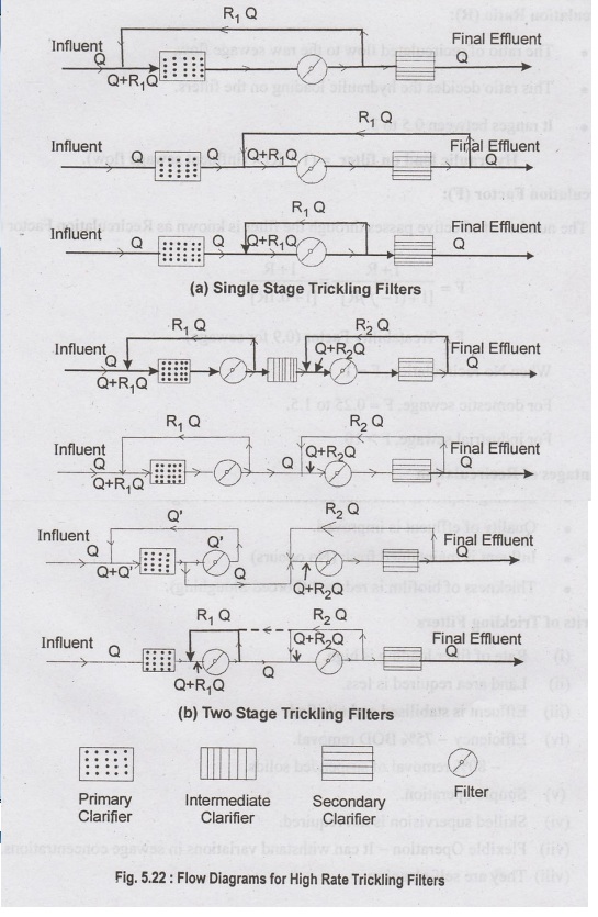
Classification of High Rate
Trickling Filter
(i)
Single-Stage High Rate Trickling Filter
(ii)
Two-Stage High Rate Trickling Filter
(i) Single Stage HRTF
•
Single stage unit consists of one primary settling tank, one trickling filter,
one bs secondary settling tank and facilities for recirculation.
•
Settling before recirculation is carried out either in primary (or) secondary
clarifier.

(ii) Two Stage HRTF:
•
Two stage filters consists of two trickling filters in series with a primary
settling tank, an intermediate settling tank (optional) and a final settling
tank.
•
Recirculation facilities are provided for each stage.
•
The effluent from first stage is applied to the second stage either after
settlement (or) without settlement.
•
An intermediate clarifier is used for settling the first stage effluent before
it is applied to the second stage filter.

Recirculation Ratio (R):
•
The ratio of recirculated flow to the raw sewage flow.
•
This ratio decides the hydraulic loading on the filters.
•
It ranges between 0.5 to 3.
Hydraulic load on filter
= (1 + R) × (influent sewage flow).
Recirculation Factor (F):
The
number of effective passes through the filter is known as Recirculation Factor
(F).

When
No recirculation, F = 1
For
domestic sewage, F = 0.25 to 1.5.
For
industrial sewage, F > 10.
Advantages of Recirculation
•
Seeding improves microbes concentration in sewage.
•
Quality of effluent is improved.
•
Influent is maintained fresh (No odours)
•
Thickness of biofilm is reduced (Forced Sloughing).
Merits of Trickling Filters
(i) Rate of filter loading is high.
(ii)
Land area required is less.
(iii)
Effluent is stabilised and nitrified.
(iv)
Efficiency - 75% BOD removal.
-
80% removal of suspended solids.
(v)
Simple operation.
(vi)
Skilled supervision is not required.
(vii)
Flexible Operation - It can withstand variations in Sewage concentrations.
(viii)
They are self-cleaning.
(ix)
Mechanical wear and tear is small as they contain less mechanical equipment.
(x)
Operates more efficiently in warm weather. Very useful in hot countries like
India.
Demerits of Trickling Filters
(i)
Head loss is high
(ii)
Automatic dosing of filters is necessary
(iii)
Construction cost is high
(iv)
Cannot treat raw sewage. Primary sedimentation (pretreatment) of sewage is a must.
(v)
Pose Operational troubles such as fly nuisane, odous nuisance and ponding problems.
Operational Problems in Trickling
Filter
(a) Fly Nuisance:
Psychoda fly grows on the filter media and may cause nuisance to the nearby
habitation.
Control:
(i) Flooding the filter with sewage for 24 hours or more will destroy the
larvae.
(ii) Using insecticides like D.D.T, Chlordane
and Benzene Hexachloride.
(b) Odour Nuisance:
Odours do not prevail in trickling filters using rotary distributors. However
when fixed nozzles are used, H2S and other odourous gases are released from the
sprays into atmosphere.
Remedy:
(i) Chlorinate the sewage to prevent H2S formation.
(ii)
Keep sewage fresh by re-circulation.
(c) Ponding Trouble:
Due to heavy growth of fungi and algae, the voids of the filter media gets
clogged and result in ponding of sewage over filter bed.
Remedy:
(i) Chlorinating sewage to kill the algae.
(ii)
Adding copper sulphate in sewage to control algae.
Water Supply And Wastewater Engineering: Unit V: Sewage Treatment And Disposal : Tag: : Classification, Construction, Design | Sewage Treatment - Trickling Filters
Related Topics
Related Subjects

Water Supply and Wastewater Engineering
CE3303 3rd Semester Civil Dept 2021 Regulation | Tag: 3rd Semester Civil Dept 2021 Regulation