Water Supply And Wastewater Engineering: Unit IV: Planning And Design Of Sewerage System
Sewer Appurtenances
Planning and Design of Sewerage System
Sewer appurtenances are those structures which are constructed at suitable intervals along a sewerage system, which helps in efficient operation and maintenance. These include:
SEWER
APPURTENANCES
Sewer
appurtenances are those structures which are constructed at suitable intervals
along a sewerage system, which helps in efficient operation and maintenance.
These include:
(1) Manholes.
(2)
Drop Manholes
(3) Lampholes
(4)
Clean-outs
(5) Street inlets (Gullies)
(6)
Catch Basins
(7)
Flushing Tanks
(8)
Grease and Oil Traps
(9)
Inverted Siphons
(10)
Storm Regulators.
(1) Manholes:
Manholes
are Masonry (or) R.C.C chambers.
Purpose
- Provides access into sewers for inspection, cleaning and maintenance works.
Location
- Provided at every bend, junction, change of gradient (or) change of sewer
diameter at suitable intervals along sewer line
Spacing
- Depends on sewer sizes (Larger diameter -
greater spacing).
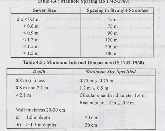
CLASSIFICATION OF MANHOLES: (BASED ON DEPTH)
(i) Shallow Manhole:
❖ Used
as inspection chambers.
❖ Depth
= 0.7 m to 0.9 m.
❖Constructed
at start of branch sewer and at places of minimum traffic.
❖Light
cover is provided at top.
(ii) Normal (or) Medium Manhole:
❖ Depth
= 1.5 m.
❖ Square
(1 mx 1 m)/Rectangular (1.2 m x 1 m) shape.
❖ Heavy
cover is provided at the top.
❖ Unlike
shallow manholes, the section does not change with depth.
(iii) Deep Manhole:
❖ Depth
> 1.5 m.
❖ Section
normally varies, the upper portion is reduced.
❖ Steps
are provided to enable workers entry to bottom.
❖ Heavy
cover is provided at the top.
Component Parts of
Manhole:
(i) Access Shaft:
❖ It
is the upper portion of deep manhole.
❖ For
rectangular manhole - size of access shaft is 0.75 m x 0.6 m.
❖ For
circular manhole - size is 0.6 m to 0.7 m.
❖ Depth
of access shaft depends on manhole depth.
(ii) Working Chamber:
❖ It
is the lower portion of manhole.
❖ Provides
working space for inspection and cleaning operations.
❖
For rectangular manhole - size of working chamber is 1.2 m × 0.9 m.
❖ For
circular manhole - size of working chamber is 1.2 m diameter.
❖ The
height of this chamber must not be less than 1.8 m.
(iii) Benching/Bottom/Invert
Portion of Manhole:
❖ The
bottom portion of the manhole is constructed in cement concrete.
❖ A
semicircular (or) U-shaped channel is generally constructed and the sides are
made to slope towards it.
❖ The
concreting is known as benching and facilitate the entry branch sewers into the
main sewer.
(iv) Side Walls:
❖ The
side walls are made of brick/stone masonry/R.C.C.
❖ The
minimum thickness of the brick walls should be 22.5 cm (9'').
❖ The
approximate thickness may be computed by using emperical thumb-rule t = 10 + 4d
(for brick walls).
t
= Thickness of wall in cm.,
d
= Depth of excavation in m.
❖ The
thickness of R.C.C walls will however be much less as compared to that of brick
wall, but RCC walls are costly than brick.
(v) Steps (or) Ladders:
❖ Steps
are generally provided for descending into deep manholes.
❖ Steps
are made of cast iron and are placed at a horizontal distance of about 20 cm
and a vertical distance of about 30 cm. Steps are embedded in walls.
vi) Cover and Frame:
❖ Cover
is generally made of cast iron material and are fixed at the top of the manhole
embedded in pavements.
❖ The
thickness of the frame is about 20 to 25 cm and is about 10 cm wide.
❖ Circular
or rectangular shape cover is provided of size 0.5 to 0.6 m & or 0.6 m ×
0.45 m respectively where & is the diameter of the cover.
❖ The
top surface of the cover also carries an arrow mark to mark the direction of
flow of sewage.
❖ The
weight of the cover and frame varies between 90 to 270 kg which depends on
traffic volume.
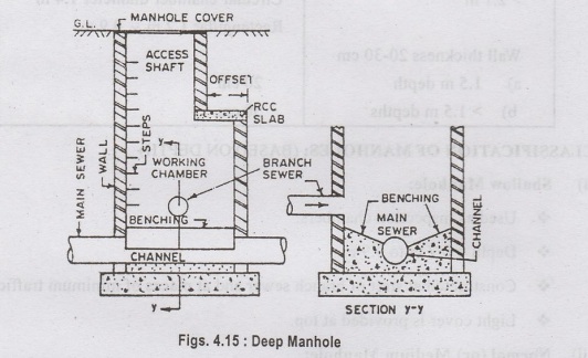
2. Drop Manhole:
❖ Branch
line is provided 0.5 to 0.6 m above main sewers.
❖ The
sewage from branch sewers is not allowed to fall directly into the manhole, but
is brought into it through down pipe taken from the branch sewer to the bottom
of the manhole.
❖ Either
vertical down pipes (drop manhole) or inclined pipes (ramp) are provided. The
vertical pipe is economical.
❖ A
manhole in which a vertical down pipe is provided is called a drop manhole.
❖ A
plug and inspection arm are provided at the point where the straight stretch of
branch sewer intersects the wall of the manhole.
❖ Sewage
from the branch sewer dips through vertical pipe and trickles over the main sewer.
Advantages:
(i)
Steep gradients of branch sewers is avoided by providing vertical drop
manholes. The cost of excavation is reduced.
(ii)
Sewage entering the manhole directly from branch sewers that are provided at
certain height is likely to fall on the working personnel, which is prevented.
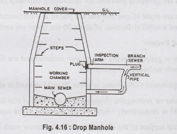
3. Lamp Holes (now
become obsolete):
❖ Openings
or hole extending from ground to sewer line through T-junction.
❖ Purpose:
(i)
For inspection (obstructions)
(ii)
For flushing sewers
(iii)
For ventilation of foul gases.
❖ These
holes permit insertion of lamps into sewers. The lamp light is viewed at
upstream and downstream ends to find any obstructions.
❖ Lamphole
consists of a vertical pipe (20 to 30 cm ) made of cast iron or stone-ware,
where o is the diameter of the vertical pipe.
❖ The
vertical pipe is surrounded by concrete.
❖ A
manhole cover is provided at the top.
❖ Location:
(i)
At bends, change in direction or gradient of sewers.
(ii)
Where manhole construction is difficult.
(iii)
Where manhole spacing is more.
4. Clean-Outs
❖ An
inclined pipe extending from the ground to the underground sewer.
❖ A
clean out is used for cleaning sewer pipes - flushing sewers (laterals) to
remove obstacles.
❖ A
clean out is provided at the upper ends of lateral sewers in place of manholes.
The functioning of a clean out is very simple. Removing the top cover and
forcing water through the clean out pipe to lateral sewers to remove obstacles
in the sewer line.
❖ If
the obstructions are large, a flexible rod may be inserted and pushed forward
and backward to remove the obstacles.

5. Street Inlets
(Gullies):
❖ Openings
on road provided at lowest point which drains rain water into storm/ combined
sewers.
❖ Provided
at spacing of 30 m to 60 m.
❖ Gullies
are connected to manholes by pipe lines.
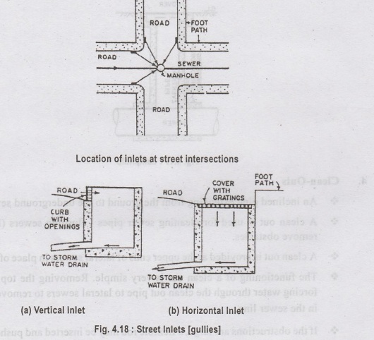
❖ A
street inlet is a simple concrete box with gratings (or) openings in vertical
(or) horizontal direction.
❖ The
inlet having vertical openings is vertical inlet and inlet having horizontal
openings is horizontal inlets.
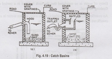
6. Catch Basins (or)
Catch Pits
❖ Catch
basins are street inlets provided with small settling basins.
❖ Grit,
sand, debris etc., do settle in these basins and their entry into the sewer is prevented
❖ A hood is provided which prevents the escape
of foul gases.
❖ Catch basins need periodical cleaning.
❖ Catch
basins are provided only in old combined sewerage system.
❖ Catch
basins are not required in modern separate sewerage system as the streets are
paved and not much debris enters the sewers. Further the foul storm water
drains is also less
7. Flushing Tanks:
❖ Device
that stores water temporarily and then throws it into the sewer for flushing
and cleaning.
❖ It
can be operated either manually or automatically.
❖ Sewers
that are laid on flat gradient or dead ends may not produce self cleansing velocity
and may be frequently blocked. This can be cleaned with the help of flushing
tanks.
❖ Quantity
of water added in one flush is about 1600 litres.
Types:
(a) Hand operated flushing operation (Manual)
Lino
(b)
Automatic Flushing Tanks
(a) Hand Operated
Flushing Operation: (Manual)
❖ A
hose pipe is provided with one end connected to the nearest fire hydrant and
another end is placed in the manhole to achieve flushing action.
❖ The
outlet and inlet ends are closed by sluice or gate valve and the manhole is
filled with water. When sufficient head builds up, both the inlet and outlet
valves are opened and flushing is achieved. (or)
❖ The
outlet end of the manhole is closed with sluice or gate valve. The incoming
sewage collects in manhole and when sufficient head builts up, the gate valve
is suddenly opened to achieve flushing.
b) Automatic Flushing
Tanks:
❖ Flushing
action is achieved automatically at regular intervals.
❖ Entry
of water is so regulated that the tank is filled in a period equal to the
flushing interval.
❖ An
overflow pipe is also provided to drain away excess water in case the tank
overflows before the flushing action starts.

❖ The
tank consists of a masonry (or) concrete chamber fitted with a water
❖ A
U-tube connects the chamber with the enlarged end of the sewer pipe.
❖ The
bell cap has a sniff hole.
❖ When
water level is below the sniff hole, water level in the U-tube is at level [Y1-Y2]
(long arm, short arm).
❖ As
the water level in the tank rises above the sniff hole, the air caught up in
the bell (compressed air) exerts pressure on water surface Y, and the water
level in the long arm is depressed.
❖ As
water level rises in tank (upto discharge level) Y, level in long arm of U- tube
depresses more and more and the compressed air caught in bell is released
through shorter arm. The siphonic action starts releasing water from the tank
into the sewer till water level falls below sniff hole.
❖ When
water level in tank falls down, air enters the bell cap and breaks the siphonic
action.
8. Grease and Oil Traps:
→
Trap chambers are used to remove oil/grease from sewage, before entering sewer
line.
→
These are located near sources which generate grease and oil (automobile repair
workshops, garages, kitchens of hotels, oil/grease indusstries etc.)
Necessity:
(i)
Grease/oil stick to sewer sides and causes obstruction or reduce sewer
capacity. (ii) Increases the possibilities of explosion in sewer lines.
(iii)
Presence of oil and grease causes difficulties in treatment.
(iv)
Presence of oil and grease on surface of waste water prevents oxygen
penetration
Principle:
❖ The
grease and oil traps consists of two chambers interconnected through a pipe.
❖ The
Inlet is provided with a grating on the top.
❖ The
oil and grease float on surface. The outlet is provided submerged to exclude oil
and grease.
❖ Combined
sand, grease and oil trap is also available.

9. Inverted Siphons: (Depressed
Sewer) (Sag Pipe)
❖ Inverted
siphons are sewer sections that are provided lower than the adjacent sewers,
(or) that drops below the hydraulic gradient line (HGL).
❖ They
are provided under the obstructions such as roadway, railway, stream, valley,
etc.
❖ Inverted
siphons should be provided only in areas where other means of passing the
obstructions are not feasible.
❖ They
are siphon tubes or pipes made of cast iron or concrete.
A
Self cleansing velocity of 0.9 m/s is achieved at minimum discharge.
❖ In
the combined flow system, three channels or pipes are provided:
(a)
Pip Pipe 1: carry minimum sanitary sewage (Channel 1)
(b)
Pipe 2: carry maximum sanitary sewage (Channel 2)
(c)
Pipe 3: carries combined flow during monsoons (Channel 3).
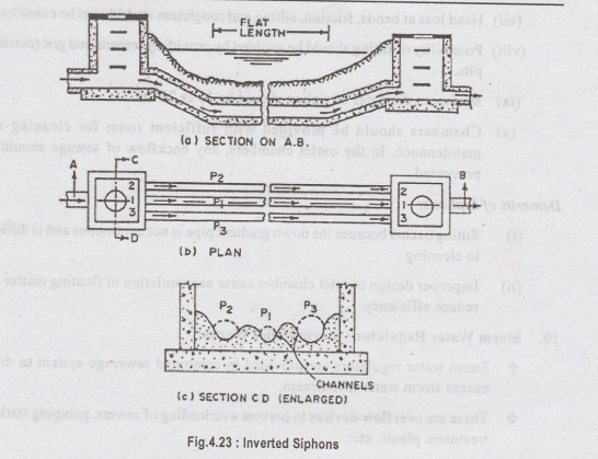
When
pipe/channel 1 overflows, the sewage enters channel 2 and
For
a separate sewerage system, two channels are provided,
(a)
Channel 1: For carrying minimum dry weather flow.
(b)
Channel 2: For carrying maximum dry weather flow.
Designing Siphon - Important
Points.
(i)
The construction should be simple.
(ii)
Direction change should be easy and gradual.
(iii)
Self cleansing velocity should be atleast 1 m/s during minimum flow. galynas
Jonnado
(iv)
Two or three parallel pipes are provided such that average flow happens in
first pipe and any excess discharge (flow) goes to the second and third pipes.
1911sm gritsoll to be invig et bobivong
(v)
Selection of pipe size depends on both average and maximum flows.
(vi)
Total pipe length should consist of straight lengths, and the lengths of falls,
bends and rise.
(vii)
Head loss at bends, friction, silting and roughness should also be considered.
(viii)
Possibility of silting should be avoided by providing screens and grit
(detritus) pits.
(ix)
Minimum diameter of siphon should be 15 to 20 cm.
(x)
Chambers should be provided with sufficient room for cleaning and maintenance.
In the outlet chambers, any backflow of sewage should be prevented.
Demerits of Siphons:
(i)
Silting occurs because the down gradient pipe is not continuous and is
difficult to cleaning.
(ii)
Improper design of inlet chamber cause accumulation of floating matter and
reduce efficiency.
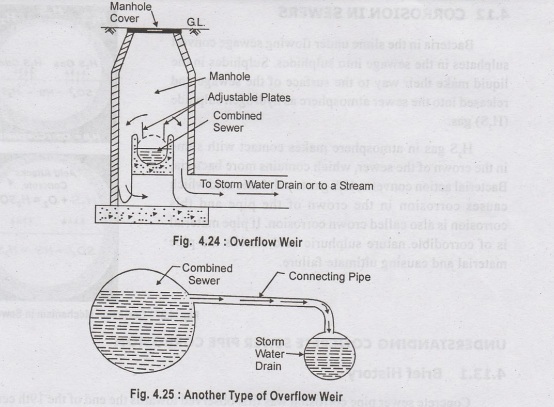
10. Storm Water Regulator / Storm
Relief Works:
❖ Storm
water regulators are provided in combined sewerage system to divert excess
storm water into stream.
❖ These
are overflow devices to prevent overloading of sewers, pumping stations,
treatment plants, etc.
Types:
(i) Overflow Weirs (Side Flow
Weirs):
❖ Masonary
chamber with overflow weir is the common type.
❖ Overflow
weirs are located where sewer approaches a water course.
❖ Single
acting (single side) (or) double acting (double side) overflow weirs can be
provided.
❖ Openings
are provided at suitable height of combined sewer and joined to storm drains.
Excess sewage flows to drains that are discharged to water course.
❖ Excess
sewage overflows the combined sewer and enters channel, carrying storm water
drain or into a stream.
❖ Adjustable
plates are provided to prevent escape of floating matter.
(ii) Leaping Weir:
❖ Opening
is provided at invert of storm drain (combined sewer).
❖ Normal
storm water flows in intercepting sewer.
❖ Excess
flows are diverted to nearby stream by the leap over combined sewers.

Water Supply And Wastewater Engineering: Unit IV: Planning And Design Of Sewerage System : Tag: : Planning and Design of Sewerage System - Sewer Appurtenances
Related Topics
Related Subjects

Water Supply and Wastewater Engineering
CE3303 3rd Semester Civil Dept 2021 Regulation | Tag: 3rd Semester Civil Dept 2021 Regulation