Water Supply And Wastewater Engineering: Unit I: Water Supply
Intake Structures (surface water sources)
Different parts, Types, Intake Towers
Intakes are the structures built in surface water sources (such as rivers, lakes, reservoirs etc.) for the withdrawal of water and discharge into conduits of the water supply schemes.
INTAKE
STRUCTURES
Intakes
are the structures built in surface water sources (such as rivers, lakes,
reservoirs etc.) for the withdrawal of water and discharge into conduits of the
water supply schemes.
Different
parts of an intake are:
(i)
Entry ports or Inlets or Penstocks: Ports are provided at
different elevations to ensure water flow during all seasons. i.e. to take care
of fluctuation during summer. The lowest entry port is placed below the lowest
water level (LWL) of the river so that water is available during dry season
also.
(ii)
Screens: The entry ports are protected with
screens to prevent entry of any debris or floating materials into the intakes.
(iii)
Intake well: It is built of masonry or concrete
which may be rectangular or circular in shape. Water drawn from the sources through
entry ports is stored in these wells which is then discharged through conduits
for water supply.
(iv)
Conduits : They are the pipelines through which
water is conveyed from the intake well to the nearby treatment plant or water
supply system.
(v)
Gate valves and control room : The water flow is
regulated by gate valves provided on top at the control tower.
(vi)
Foot bridge: A foot bridge is provided on top of the
intake tower for access.
Factors governing the location of
site for intakes:
The
site chosen for intakes should be preferably
(i)
Near the treatment plant
(To
reduce the cost of piplines)
(ii)
At the purer zone of the surface source
(To
reduce the water treatment cost)
(iii)
At the upstream side of source
(iv)
Not near any waste water or sewage disposal points.
(v)
Provide greater withdrawal of water including expansions in future.
(vi)
Provide water even during dry seasons
(vii)
Not near any navigation channel
(viii)
Should not get flooded.
TYPES OF INTAKES
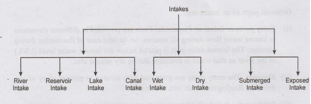
1.
River Intakes
•
Located on the upstream side of rivers, where pollution is minimum.
•
Located inside the river or on river bank such that sufficient water depth is
available to meet the demand during dry seasons also.
•
Sometimes, weirs are constructed across the rivers to increase the water level.
Classification
of river intakes
(i)
Twin well type
(ii)
Single well type
(i) Twin well type of
River Intake Structure
This
is the common type of river intake constructed on non-alluvial rivers
The
structure consists of
(i)
An inlet well
(ii)
An inlet pipe
(iii)
A jack well

Inlet
well or intake or collector well is circular built of concrete or masonry
located on river bed such that water is available during low flows. A foot bridge
is provided for access from the river bank. River water enters the inlet well
through openings or ports provided at various levels and protected by screens
to exclude entry of floating debris. The flow into the entry ports is regulated
from the control tower using gate valves. The intake well is connected to jack
well (sump well) constructed on the river bank, by a RCC intake pipe. The
bottom portion of intake well below the level of the intake pipe is used for
the accumulation of silt and sediment. The deposited silt is periodically
removed either manually or mechanically and it is ensured that the silt does
not enter the intake conduits. The pipe is provided at a gentle slope and the
flow through the pipe is under gravity at atmospheric pressure. The pipe
diameter is chosen based on the discharge capacity. Water entering the jack
well is lifted by pumps and fed into the main lines of water supply system.
(ii) Single well type of a River
Intake
This
type of intake is constructed on alluvial rivers where weirs or approach
channels are constructed to increase the water level.
In
this intake, there is no separate inlet well or inlet pipe(as in Twin Intake).
The opening ports with bar screens are provided in the jack well. Itself. Water
entering the jack well is more clear.
Sediments, if any gets deposited in the bottom of jackwell which is
periodically cleaned manually by stopping the flow.
2. Reservoir Intake
•
Located on the upstream side of earthern or masonry dams where maximum depth of
water is available.
•
It is similar to a river intake, except that the entry ports of river intakes
are replaced here with intake conduits.
•
The intake conduits which are installed at different levels withdraw the water
from reservoir and let it into a common conduit (inside the intake well or
tower) which conveys the water to the sluiceway tunnel downstream.
•
The flow of water into the intake conduits is regulated by valves operated from
control room.
•
The access to the intake is provided through a foot bridge.
•
The arrangement is similar to a dry intake tower.
•
As the intake well remains dry, it facilitates easy operation and inspection.

Fig.1.15 Reservoir Intake
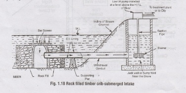
3. Lake Intake
•
Similar to reservoir intakes if the water depth is reasonable
•
At shallow waters, Lake intakes are provided as submerged intakes.
•
Submerged intakes are constructed as cribs or bell mouths.
•
The cribs are made of heavy timber framework with cast iron or mesh grating on
top. It protects the intake conduit from damage.
4. Canal Intake
•
The intake well is located in the bank of canal.
•
The water enters the intake well through a port protected with coarse screen,
provided at minimum water level in the canal.
•
The water from the chamber is then conveyed through a outlet (withdrawal)
conduit to the distribution system.
•
The inlet end of the outlet conduit is of bell mouth shape protected with a
fine screen.
•
An outlet valve is provided to control the flow which is operated from top.
•
The flow through the outlet pipe may be under gravity or by pumping.
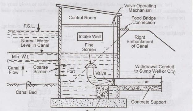
Fig.1.16 Canal Intake
5. Submerged Intake
•
Such intakes are placed in streams or lakes where there are deep waters and
very less sediments.
•
This consists of a simple concrete block
or a rock filled timber crib supporting the starting end of the withdrawal
pipe. The intake opening is protected by screen.
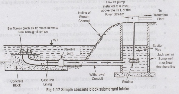
The
intake opening is kept about 2 m above the bottom of lakes to avoid entry of
sediments. These intakes are cheap and do not obstruct navigation. They are widely
used for small water supply projects.
The
disadvantage of these intakes is that they are not accessible for cleaning,
repairing etc.
INTAKE
TOWERS
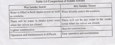
Types
of Intake towers:
(i) Wet intake tower
(ii)
Dry intake tower
(i) Wet Intake
Towerse
•
In wet Intake Towers, water is filled in both the intake well (chamber) and the
conduits.
•
It consists of a concrete circular shell filled with water and vertical inside
shaft connected to the withdrawal pipe.
•
Openings (Ports) are provided in the concrete shell as well as the vertical
shaft for the entry of water. The flow is regulated by gate valves.
•
Water from the withdrawal pipe flows to the nearby water treatment plant either
under gravity or by pumping.
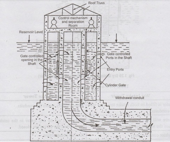
Fig. 1.19 Wet Intake Tower(Standing in river or resservoir)
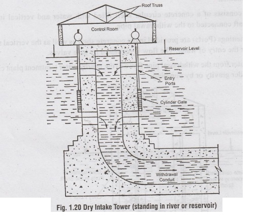
(ii) Dry Intake
Towers
•
In dry intake towers, water is directly drawn into withdrawal conduits through gated
entry ports.
•
There will be no water in the tower.
•
Heavier construction is required than the wet intake towers.
•
(It facilitates easy operation and
maintenance.
Types of conduits
Depending
upon the flow conditions, the conduits are categorised as
(1)
Gravity conduits
(2)
Pressure Conduits
(1) Gravity conduits / Open
channels
•
Water flows under gravity at atmospheric pressure
•
The hydraulic gradient line will coincide with the water surface and will be parallel
to bed of conduits.
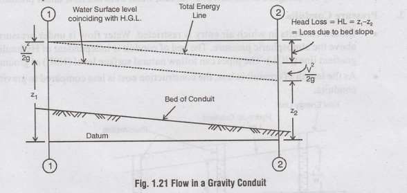
•
Conduits are provided at gradual slope. They cannot follow the natural surface
level.
•
The length of conduit is more which increases the cost of construction.
•
In order to maintain the HGL, these conduits have to be taken on trestles
constructed across Valleys/depressions. It further increases the cost.
•
The advantage is that no pumping is required.
Different
forms of gravity conduits are:
(i)
Canals
(ii)
Flumes
(iii)
Aqueducts
Canals:
•
Open channels constructed by cutting high ground and filling low grounds.
•
They are lined or unlined depending upon the slope/velocity/ water quality /
losses.
Flume:
•
Open channels supported above ground over trestles.
•
Used to convey water across valley or depressions or obstructions
•
Made of masonry, RCC, metal, wood
•
Usually regtangular or circular in cross-section
Aqueducts:
•
Closed, rectangular or circular or horse shoe section
•
Built of Masonry or RCC.
•
Usually covered/closed.
•
As they are designed to run half or 3/4th full, water does not flow under
pressure
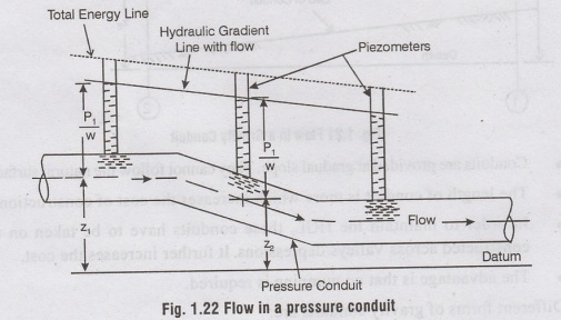
2. Pressure Conduits
•
Closed conduits in which air entry is restricted. Water flow is under pressure
above the atmospheric pressure. The bed of conduit is independent of Hydraulic
gradient line (HGL). The pipes can follow natural surface level (NSL) of ground
•
As the length of conduit is less, the construction cost is less compared to
gravity conduits.
•
As pressure conduits follow the natural surface level, deep excavations are n
required (as in the case of gravity conduits which follow HGL) and therefore is
economical. But in depressions, pumping may be required to achieve pressu flow
which increases the cost.
•
Pressure conduits may be in the form of pressure aqueducts/pressure tunne
preferably circular in shape.
•
As the conduits are closed, there are less chances of water pollution.
Water Supply And Wastewater Engineering: Unit I: Water Supply : Tag: : Different parts, Types, Intake Towers - Intake Structures (surface water sources)
Related Topics
Related Subjects

Water Supply and Wastewater Engineering
CE3303 3rd Semester Civil Dept 2021 Regulation | Tag: 3rd Semester Civil Dept 2021 Regulation