Water Supply And Wastewater Engineering: Unit II: Water Treatment
Clariflocculator
coagulation sedimentation plant with Solved Example Problems | Water Treatment
Simple in operation, requires less space and cheaper. However dosage control is difficult. Coagulant (powder) is kept in hopper bottom of tank. Agitating plates prevent arching of coagulant.
CLARIFLOCCULATOR
The
constituents of a coagulation sedimentation plant or Clariflocculator are:
(1)
Feeding device
(2)
Mixing device or mixing basin
(3)
Flocculation tank or flocculator
(4)
Settling or Sedimentation tank
A
Clariflocculator containing all these four units is shown in figure
p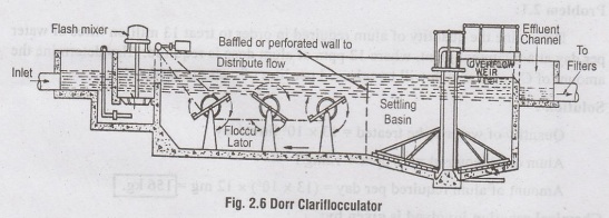
The
chemical coagulant is fed (either dry or solution) into raw water through the
feeding device.
The
(water + coagulant) mixture is thoroughly mixed and agitated in the Mixing
The
coagulant causes the very fine suspended and colloidal particles to agglomerate
and form 'floc', which happens in the flocculation tank.
The
flocculated water is finally passed into the sedimentation tank where these
flocculated particles settle and are removed.
Each
of these four units is discussed in detail below:
1. Methods of feeding coagulants /
Feeding devices
a)
Dry feeding
b)
Wet feeding
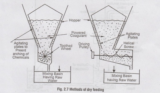
a) Dry feeding
The
chemical coagulant is fed into raw water in powdered form.
Simple
in operation, requires less space and cheaper. However dosage control is
difficult. Coagulant (powder) is kept in hopper bottom of tank. Agitating
plates prevent arching of coagulant. The dosage is regulated by the speed of
toothed wheel/helical screw which in turn is controlled by venturi device
installed in the raw water pipes.
The
quantity of coagulant released is in proportion to the quantity of the raw
water entering the mixing tank.
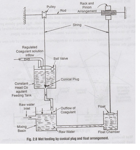
(b) Wet feeding:
The
chemical coagulant is fed into raw water in solution form. The wet feeding
equipments are costlier, but they can be easily controlled and adjusted. The
coagulant solution is prepared and stored in a tank, from where it is allowed
to trickle down into mixing tank. A conical plug type arrangement is used to
regulate the rate of coagulant discharge proportionate to the rate of raw water
flow. The mixing basin and float chamber are interconnected so that water level
is same in both. As the flow of water increases, the depth of water in mixing
basin as well as float chamber increases and thereby lifting the float. As
float rises, the pinion and pulley lifts the conical plug allowing more flow of
coagulant solution into mixing basin. When water flow decreases, conical plug
descends down and reduces the coagulant feeding rate. Thus coagulant dosage is
automatically controlled. The chemical which are corrosive in nature create
problems in wet feeding.
2. Mixing Devices
After
addition of coagulant to raw water, the mixture should be thoroughly and
vigorously mixed so that the coagulant gets fully dispersed into water. This
violent agitation is achieved by mixing devices such as centrifugal pumps,
compressed air and mixing basins. The mixing basins are normally adopted and
they are of the following two types:
a)
Mixing basins with baffle walls
b)
Mixing basins equipped with mechanical devices
(a) Mixing basins with baffle walls:
Rectangular tanks which are divided by baffle walls. The baffles are provided
in such a way that the water flows in the following pattern.
(i)
Horizontally around the ends of baffles.
(ii)
Vertically over and under the baffles.
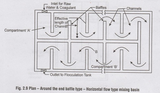
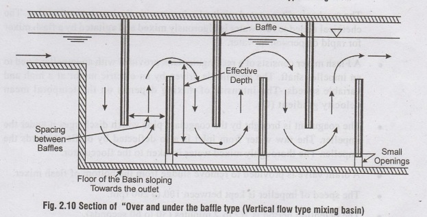
The
disturbances/ hindrances created by the baffles to the flow creates sufficient agitation and mixing The velocity of flow is
controlled to a value of 0.15 to 0.45 m/s.
The
detention period is 20 to 50 minutes. They are less efficient and are used only
i small. WTPs. Awoll
b) Mixing basins with mechanical
devices - Flash Mixer
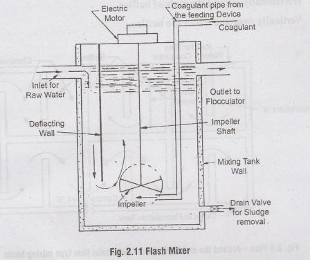
•
The mechanically agitated mixing basins provide the best type of mixing. T
chemical added to raw water is vigorously mixed and agitated by a flash mix for
rapid dispersion in water.
•
A Flash mixer consists of a rectangular tank provided with an impeller fixed an
impeller shaft. The impeller is driven by an electric motor at a high a
variable speeds. The intensity of mixing depends on the temporal me velocity
gradient (G).
•
The coagulant is brought by the coagulant pipe which discharges it under
impeller. The raw water from inlet is also deflected by baffles towards
impeller. The thoroughly mixed water is taken to the flocculator.
•
A drain valve is provided to remove sludge from the bottom of flash mixe
•
The speed of impeller is kept between 100 to 200 rpm.
•
The detention period is 1/2 to 2 minutes (30 to 60 seconds).
•
The value of G is 300 s-1
•
Power required is 1 to 3 Watts per m3/hr of flow.
c) Centrifugal pump
Raw
water is pumped into the settling tank. Chemical is added to the suction line
of
When
water with coagulant passes through the impeller of pump, mixing is created.
d) Compressed air agitation
In
this, raw water and coagulant are agitated vigorously by diffusing compressed
air from bottom of the mixing basin.
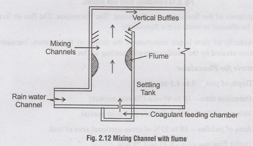
(e) Narrow mixing channel with
flume
The
Coagulant is fed from the feeding tank'
The
turbulance caused by vertical baffles and flumes mixes the chemical thoroughly.
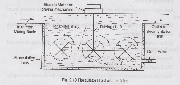
3. Flocculation Tank or Flocculator
The
violent agitation in a Flash Mixer should be followed by a slow and gentle
stirring to permit agglomeration of floc particles.
From
the mixing basin, water is taken to the flocculator where it is given slow and
gentle stirring motion.
They
are rectangular tanks with paddles operated by electric motors. The water from
the flocculator is taken to the sedimentation tank.
The
paddles rotate at 2 to 3 rpm speed. The detention time is 20 to 60 min (30 m
normally). The velocity gradient is 20 to 80 s1. The clear distance between
paddles an wall or floor is 15 to 30cm.
The
purpose of the flocculator is to facilitate 'floc' formation. The floc so forme
should not be allowed to settle in the flocculator.
The
velocity of flow is not important in the design of flocculators, because th
rolling motion created by the paddles prevents settling of floc.
Design Criteria for Flocculator
(i)
Depth of tank - 3 to 4.5 m
(ii)
Detention time - 10 to 40 min (30 min normal)
(iii)
Velocity of flow - 0.2 to 0.8 m/s (0.4 m/s) normal.
(iv)
Area of paddles - 10 to 25% of cross-sectional area of tank.
(v)
Outlet flow velocity - 0.15 to 0.25 m/s
(vi)
Power consumption - 10 to 36 KW/mld.
(vii)
Velocity gradient (G): 10 to 75 s-1
4. Sedimentation tank (Clarifier)
Similar
to plain sedimentation tanks, except that the detention period is less (2 to 4
hrs) and has a higher surface loading (overflow) rate of 1000 to 1250 1/hr/m2
or 24 to 30 m3/d/m2 of plan area.
COMBINED
COAGULATION-CUM-SEDIMENTATION TANKS
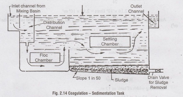
It
is a combination of coagulation and sedimentation tank. It consists of a plain
floc chamber (without mechanical devices) followed by a sedimentation tank.
Detention period for floc chamber is 15 to 40 minutes and for settling tank is
2 to 4 hours. The depth of floc chamber is half the depth of settling tank. The
water from mixing basin enters this tank and the clarified water comes out at
the outlet end. The design is similar to a sedimentation tank except that it is
deeper 3 to 6 m. They are cleaned at 6 months interval.
Problem 2.2:
Design
a coagulation-cum-sedimentation tank with continuous flow for a population of
60,000 persons with a daily per capita water allowance of 120 litres. Make
suitable assumptions where needed.
Solution:
1. Design of Settling Tank
Average
daily consumption = Population × Per capita demand
=
60,000 x 120 = 7.2 × 10⁶ litres
Maximum
daily demand = 1.8 × Average daily demand
02
= 1.8 × (7.2 × 106) = 12.96 × 10⁶ litres
Assuming
detention time of 4 hours (between 2 to 4 hours)
Capacity
or Volume of Tank = Discharge x Detention Time
Volume
= 12.96×10⁶ / 24 x 4
=
2.16 x 10⁶ litres = 2.16 x 10³ m3
Assuming,
surface overflow rate as 1000 litres /hr /m2 (between 1000 to 1250 l/hr/
Q
= 12.96 × 10⁶ l/d = 540 x 103 1/hr
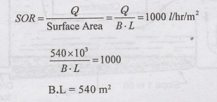
Assuming
width of tank as 12 m,
12
x L = 540 m2
L=
45 m
Volume
= L x B x H = 2.16 × 10³ m3
45
x 12 x H = 2.16 x 10³
H
= 4 m
Extra
depth for sludge storage (1 in 50 slope) = 45/50 = 0.9m
Assume
Free Board = 0.5 m
Overall
depth = water depth + sludge storage + free board
=
4 m +0.9 m + 0.5 m
=
5.4 m
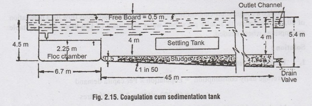
Provide
settling tank of dimensions 45 m x 12 m x 4m
2. Design of the Floc chamber
Depth
of floc chamber = ½ x depth of settling tank
1/2
x 4.5 = 2.25 m
Assuming
period of flocculation (detention period) as 20 minutes. (between 15 to
40
min)
Volume
or Capacity of chamber =Q x Detention time
12.96×10³
/24×60 =180m3
Area
required = Volume / depth = 180/2.25 = 80m3
Using
same width = 12 m,
Length
of flocculation chamber = 80 /12 = 6.67 m
The
dimensions of Floc chamber are = 6.7 m x 12 m x 2.25 m
Water Supply And Wastewater Engineering: Unit II: Water Treatment : Tag: : coagulation sedimentation plant with Solved Example Problems | Water Treatment - Clariflocculator
Related Topics
Related Subjects

Water Supply and Wastewater Engineering
CE3303 3rd Semester Civil Dept 2021 Regulation | Tag: 3rd Semester Civil Dept 2021 Regulation